VMware vRealize Automation Part 6 – System / Infrastructure & Fabric Administrators

There are various types of Access Roles within vRA, each with different permissions that exist within vRA (more roles introduced through the IaaS server). Some are System-Wide, some are Tenant-Wide and some are Business Group wide roles. First part of this post, we’ll briefly cover all the different roles available within vRA, the order they are created and each roles remit followed up by a brief look at different architectural concepts available within vRA IaaS service to understand how the resources are mapped to users. The next part of the post will then look at the 3 system wide roles (System Admin / Infrastructure Admin / Fabric Admin) and what need to be set up under each user role during the initial deployment and in what order. Lets take a look at the roles at first. There are multiple roles each with a certain set of privileges within vRA. The number and the types of roles can get very confusing and often, I’ve not been able to remember every role and all of their abilities properly with the order of when and how they need to be created. So, I thought I’d document it all in one place as follows. Roles

Now the various user roles available within vRA and what they do and what order you create them is clear, one may wonder what the heck are those endpoints, business groups, fabric groups…etc. A fair  question, and the user roles discussed above may not fully be understood until these essential vRA components & concepts are also understood. A typical vRA environment provides a complete multi – tenancy deployment capability so that an ISP for example, can deploy vRA to automate IaaS service provisioning to a number of its customers, each of which may have a dedicated, separate tenant, associated with each client’s own directory service system, all hosted securely on the same vRA platform. And then, vRA uses a number of specific internal constructs to map external resources (such as vCenter servers with compute clusters, vCloud Director instances with Org VDCs…etc) to a set of business users in order to grant them role based access to those resources. This require understanding of those constructs and in what order they are created which, I’ve found to be pretty damn convoluted when I first started off (to be honest, I still tends to forget the order if I stay away from working with it for a while). So, I’ve thought to summarise all the key constructs used by vRA, and how they are used to map external resources and the order of setting those up, using a simple example below. Architecture Example

System-Wide Roles & Initial Configuration

Ok, now that we’ve established a reasonable understanding of the vRA IaaS platform architecture with regards to Multi tenancy and the types of users & groups involved, lets look at how to setup things, in the exact order they need to be done, following on from the previous posts. (We configured up to creating the Tenants and specified the Tenant Administrators within the post 3) Once you’ve completed the IaaS server components specified within the post 4,  you can carry on with the following tasks, in the specified order to complete the IaaS configuration. For the purpose of the IaaS configuration from here on, we are assuming that we are configuring the Default Tenant (vSphere.local). If you decide to create additional tenants, they can also be configured the same way, however the URL you need to login to non default Tenants would be “https://<FQDN of the vRA Appliance>/shell-ui-app/org/<Tenant Name>”.

    1. System Administrator – Setup Infrastructure Administrators for the IaaS platform
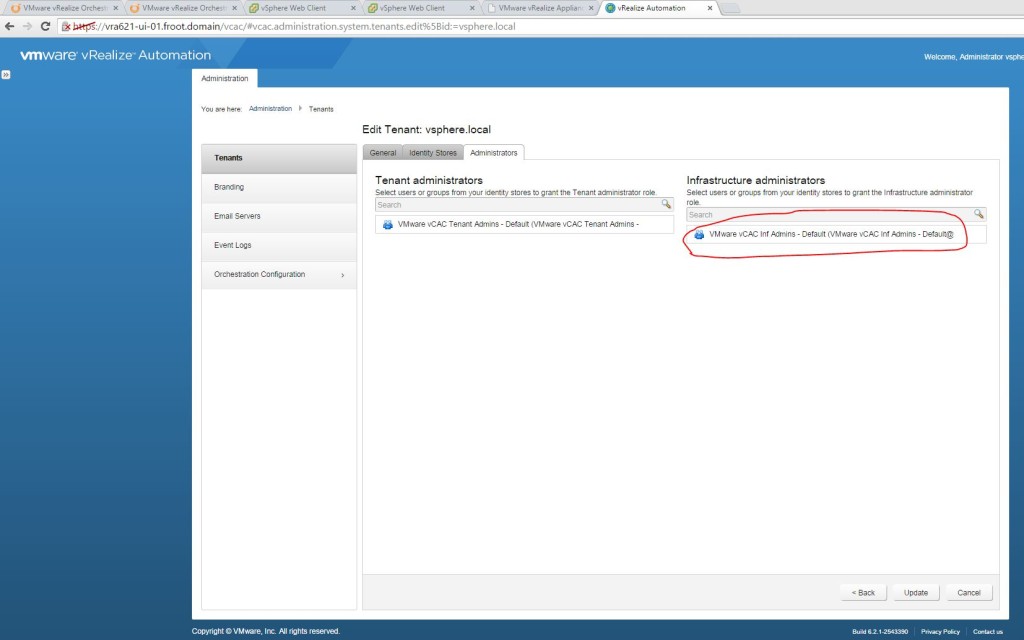
      1. Login with the System Administrator privileges (Administrator@vsphere.local) to vRA UI for the default tenant (URL “https://<FQDN of the vRA Appliance>/shell-ui-app”). Note that the Infrastructure Administrators section inside the Default Tenant is only enabled because we’ve deployed the IaaS server component on top of the vRA appliance.5.2
      2. Specify the Active Directory Group to be given the Infrastructure Administrator privileges here.  (I have an Active Directory group I will be using here named “VMware vCAC Inf Admins – Default” & a specific user as a member of that group called “<Domain>\inf-admin” which will inherit this permission through this group. 6.1.2
    2. Infrastructure Administrator
      1. Login as the newly setup Infrastructure Admin to the default tenant on vRA (URL “https://<FQDN of the vRA Appliance>/shell-ui-app”) and follow the Goal Navigator (Click on the >> on the top left). Else, the steps are as follows
      2. License the vRA IaaS component (Administration->Licensing) – same vRA license code as used in initial vRA appliance configuration as described here.
      3. Setup Endpoints & Credentials
        1. Note: Its best practise to always create the endpoint first here before installing the agents (in this example, the agent has already been installed during the IaaS server deployment)
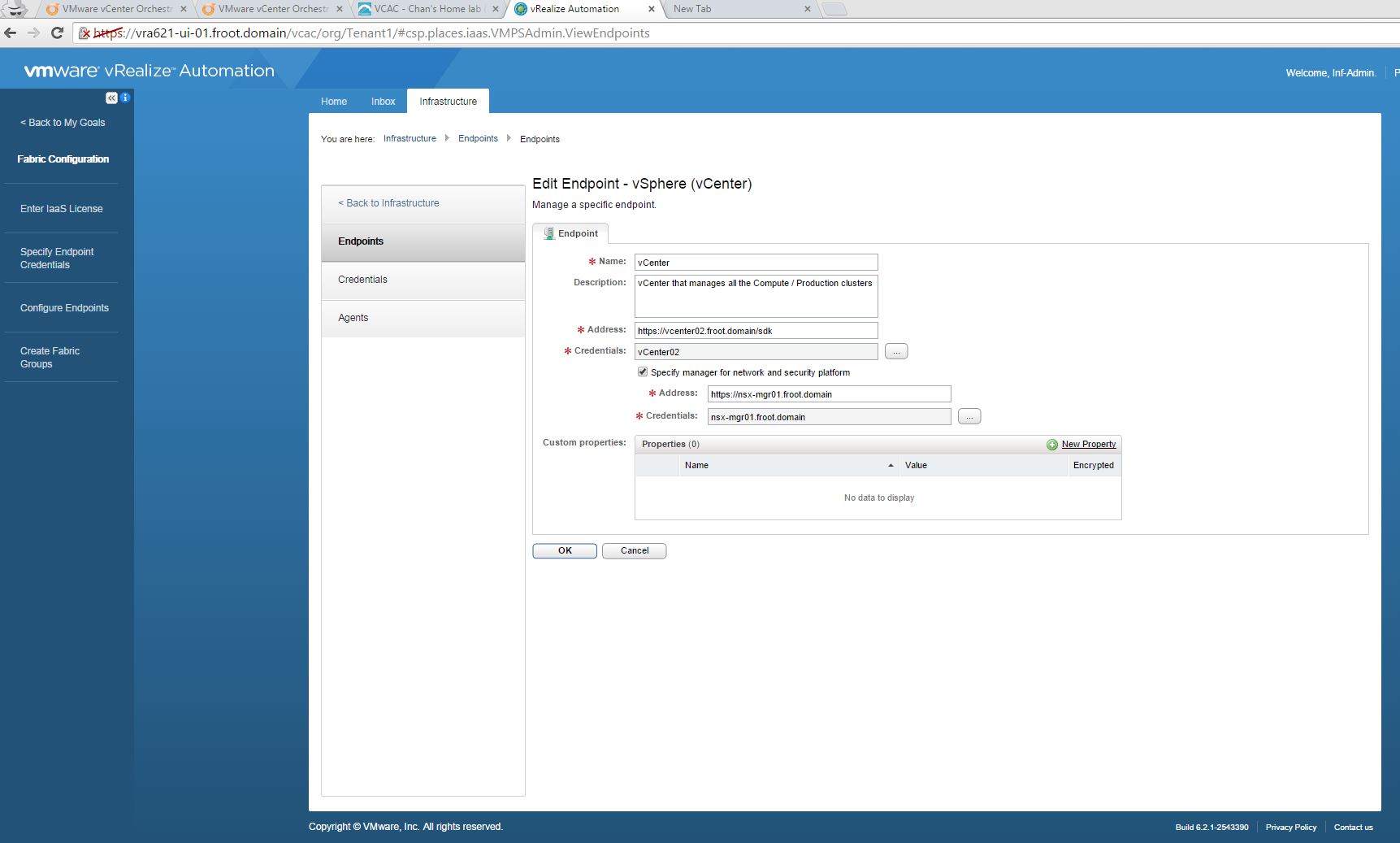
        2. vCenter Endpoint
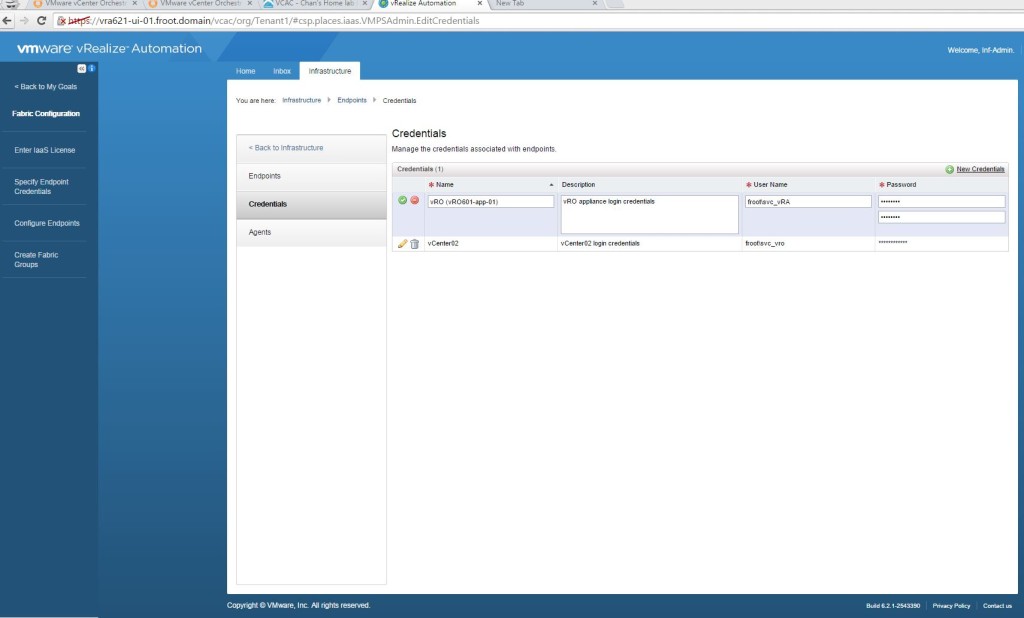
          1. Create the vCenter credentials. I’m using the vRA service account (domain\svc_vRA) which I’ve permissioned as a vCenter Administrator here. 6.2.3.1.1 new
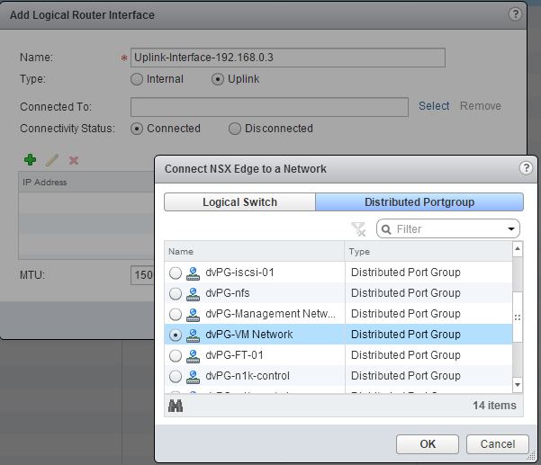
          2. Add a vCenter endpoint using Infrastructure->Endpoints->New Endpoint->Virtual->vSphere (vCenter URL is https://vCenter FQWDN/sdk). Note that the endpoint name here for vCenter should match the endpoint name defined during the IaaS server vSphere agent component deployment (covered in the post 4 of this series. Screenshot is here). If the 2 names are different, vCenter endpoint will not connect.   6.2.3.1.2 new
        3. vRO Endpoint Setup for IaaS functions
          1. Create the vRO credentials. I’m using the vRA service account (domain\svc_vRA) which I’ve also permissioned as a vRO Administrator user (when setting up the vRO in post 5, we mapped an AD administrative group as a vRO admin group of which the svc_vRA user is made a member of) 6.2.3.2.1
          2. Add a vRO endpoint using Infrastructure->Endpoints->New Endpoint->Orchestration->vCenter Orchestrator
            1. Use the vRO URL as https://vRO FQWDN:8281/vco
            2. Ensure to add a custom property VMware.VCenterOrchestrator.Priority with a value of 1 6.2.3.2.2.2
            3. Then go to the Infrastructure->Endpoints and hover the mouse over the vCO endpoint and select Data Collection. Start collection and verify success 6.2.3.2.2.3
        4. NSX Endpoint
          1. Note: before adding the NSX endpoint, the NSX plugin for vRO must have been configured correctly (we did this in the previous post of the series – step 9.3.1)
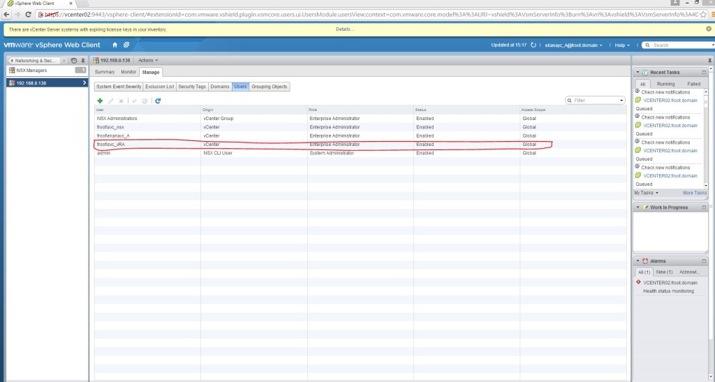
          2. Set the vRA service account (Domain\svc_vRA) with appropriate NSX privileges within the NSX manager via  the web client.   6.2.3.3.2
          3. Create NSX credentials by specifying the Domain\svc_vRA account (mapped as NSX Enterprise Administrator above)   6.2.3.3.3
          4. Go the configured vCenter endpoint, edit and select “Specify manager for network and security platform” checkbox and specify the NSX manager FQDN as the address and the NSX credentials specified above                         6.2.3.3.4
          5. We need to start a NSX data collection here and verify which we cannot do until the fabric administrator account is created and logged in which we will do later on below. (another weird design within vRA where Infrastructure admins can initiate data collection of vCloud Air and vRO endpoints but only Fabric Admin can do the same for vCenter & NSX endpoints….).
        5. Additional endpoints such as vCloud Air Endpoint will be covered in a separate post in the future.
      4. Create Fabric Groups & Fabric Administrators
        1. Go to Infrastructure->Groups->Fabric Groups and create a new Fabric Group
        2. Select an AD group as Fabric Administrators and the compute cluster to be mapped to this Fabric Group. (refer to the diagram above for resource mappings) – note that with previous version of vRA / vCAC, you were NOT able to add an AD group here (had to be a single AD user). Appears fixed in this version.6.2.4.1
        3. That’s it. You now have a fabric group with a fabric administrator group defined. Next step is to login as the Fabric Admin and complete his tasks.
    3. Fabric Administrators – Part 1
      1. Note: I have an AD user named Domain\fab-admin who is a member of the Fabric Administrators AD group used above and will be using this user account to login to vRA to perform with for all Fabric Administrators tasks.
      2. Verify data collection for the vSphere endpoint and the NSX endpoint
        1. Login to vRA as the Fabric Admin. (URL “https://<FQDN of the vRA Appliance>/shell-ui-app”)
        2. Go to Infrastructure->Compute resources and hover the mouse over the compute cluster and select data collection and ensure Compute/Inventory/State/performance / Networking & Security (NSX) data collections have succeeded. (I normally change the interval to 1 hour)   6.3.2.2
        3. If the NSX data collection is not complete, invoke a collection manually via request now.
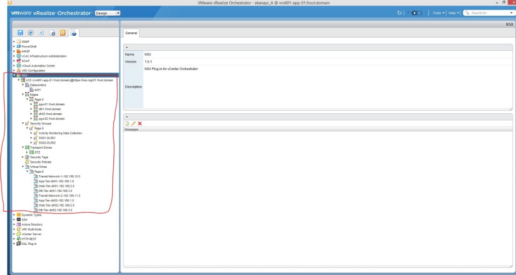
        4. Once the NSX collection is successful, login to the vRO client (you can get the client using https://vRO FQDN:8281/vCO) and go to the Inventory tab
        5. Reload by pressing F5 and expand the NSX field on the left to confirm vRO is populated fully with the NSX configuration of your environment   6.3.2.5
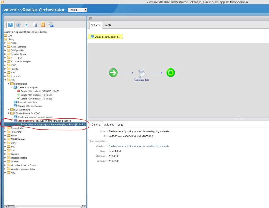
        6. If you are planning to use NSX security policy features from vRealize Automation, an administrator must run the Enable security policy support for overlapping subnets workflow in vRealize Orchestrator. The security policy support for overlapping subnets workflow is applicable to an VMware NSX 6.1 and later endpoint. For 6.1, 6.1.1, and 6.1.2, you must run this workflow only once to enable the AppliedTo flag in the service composer. For VMware NSX 6.1.3 and later, you do not need to run the workflow because this support is enabled by default. – As my NSX version is 6.1.2, I’ve run this workflow as follows.   6.3.2.6
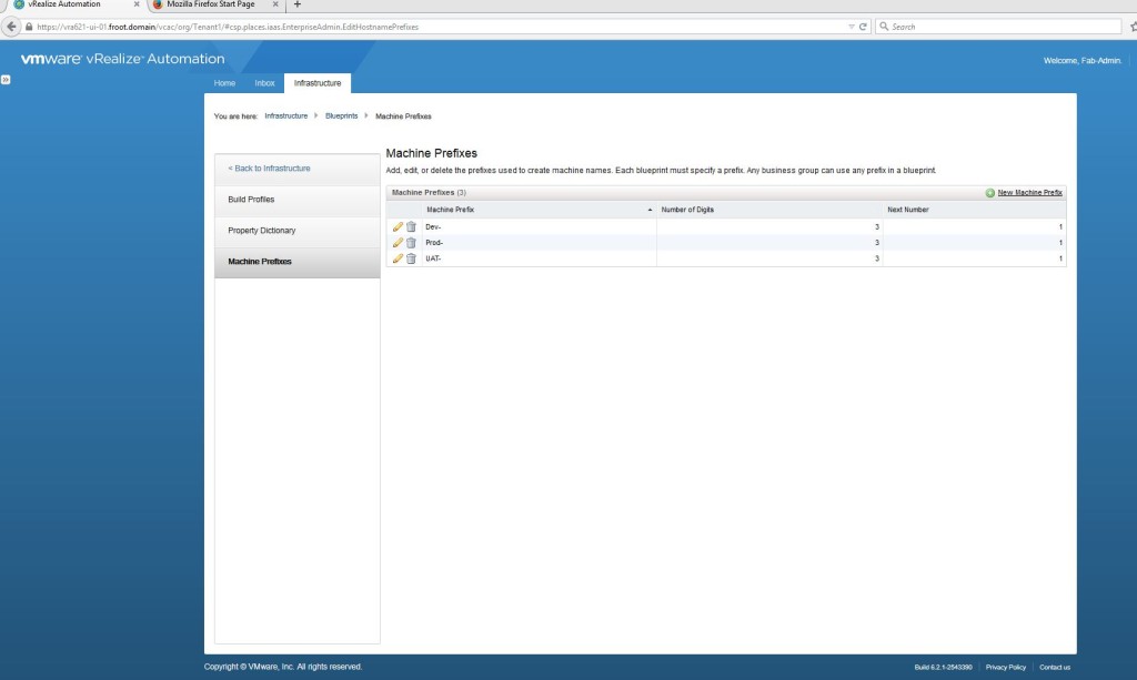
      3. Create the Machine prefixes
        1. Some points on Machine Prefixes
          1. Machine prefixes are mandatory  and are used to generate names of vRA provisioned machines.
          2. They can be shared across all Tenants
          3. Consist of a base name followed by a counter (i.e. Prod-XXX where XXX is a number will produce machine names such as Prod-001, prod-002…etc.
          4. When business groups are created by Tenant admins, you need to assign a default machine prefix to each.
          5. Every blueprint must have a machine prefix or share the default machine prefix of the business group
          6. Must conform to DNS naming restrictions (ASCII letters A-Z and digits 0-9 with no special characters).
          7. If used for a Windows machine, need to be < 15 characters in length.
        2. Go to Infrastructure->Blueprints->Machine prefixes and create a machine prefix.    6.3.3.2
    4. Tenant Administrators – Part 1
      1. Note: Next up in the list of to do things is for the Fabric Admin to create the reservations, reservations policies & network profiles. But thanks to somewhat less than ideal role allocation available within vRA (VMware: Hope you are listening??), you cannot do those steps without having the business groups created first which Fabric Admins cannot do. So we have to login as a Tenant Admin briefly here and create the business groups before we can resume with the rest of the fabric admin’s duties.
      2. Create Business Groups
        1. Important points on Business Groups
          1. A business group associates a set of services and resources to a set of users such as a line of business, department or other organizational unit.
          2. Reside within a Tenant
          3. Created by a Tenant Admin of that particular Tenant
          4. To request machines, a user MUST belong to an appropriate business group with the appropriate privileges (Business Group User)
        2. Login as Tenant Administrator (I have a dedicated tenant admin domain account named Domain\Tenant-Admin which is a member of the Tenant Admin AD group which we had earlier permissioned with the tenant Admin privileges). – The login URL is “https://<FQDN of the vRA Appliance>/shell-ui-app”
        3. Go to Infrastructure->Groups->Business Groups and create a new business group.
          1. AD container can be the location where machine objects would be created
          2. Group Manager / Support Role / User Role can all be AD groups (this wasn’t possible with earlier versions of vCAC) or an AD user account. I’ve used AD groups here as its neater and allows RBAC. I’ve then created individual user accounts (Domain\bg-admin, Domain\bg-support, Domain\bg-user) that have been nested in the relevant AD group to inherit permissions.
          3. Create Custom properties (if applicable)
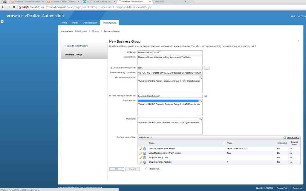
            1. Custom properties are quote useful in manipulating where machine accounts gets created within vCenter, relevant snapshot policies…etc. We will look at Custom properties in detail a little later on but for now, will create few basic custom properties as shown below.   6.4.3.3
        4. That’s it. You now have a Business Group created that can be used within a reservation so we will now go back to finishing off fabric admins duties.   6.4.2.4
    5. Fabric Administrators – Part 2
      1. Create Reservations
        1. Key Points
          1. Reservation is a share of provisioning resources allocated by the Fabric Admin (from a Fabric group) to a particular business group to use.
          2. Each reservation is for a single business group
          3. Each machine or blade can only belong to a single reservation
        2. Login as the fabric administrator (URL is “https://<FQDN of the vRA Appliance>/shell-ui-app”)
        3. Go to Infrastructure->Reservations and create a new Reservation from the previously created Fabric Group to be used by the previously created Business Group.    6.5.1.3
        4. Select the Resources tab and allocated a portion of the available storage & Memory to be included within this reservation   6.5.1.4
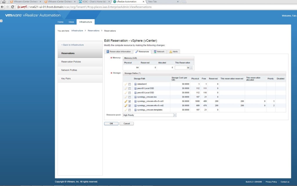
        5. Select a VM Network by selecting the appropriate VM Network Port group Name within the Network Tab. (Note that NSX specific networking will be setup later)   6.5.1.5
      2. Create Reservation policies
        1. Key points
          1. Reservation Policy restricts a blueprint to a subset of the available resource & storage reservations (a Blueprint which is created at Tenant level can otherwise deploy to any reservation within that template)
        2. Go to Infrastructure->Reservations-> Reservation Policies and create a reservation policy. 6.5.2.2
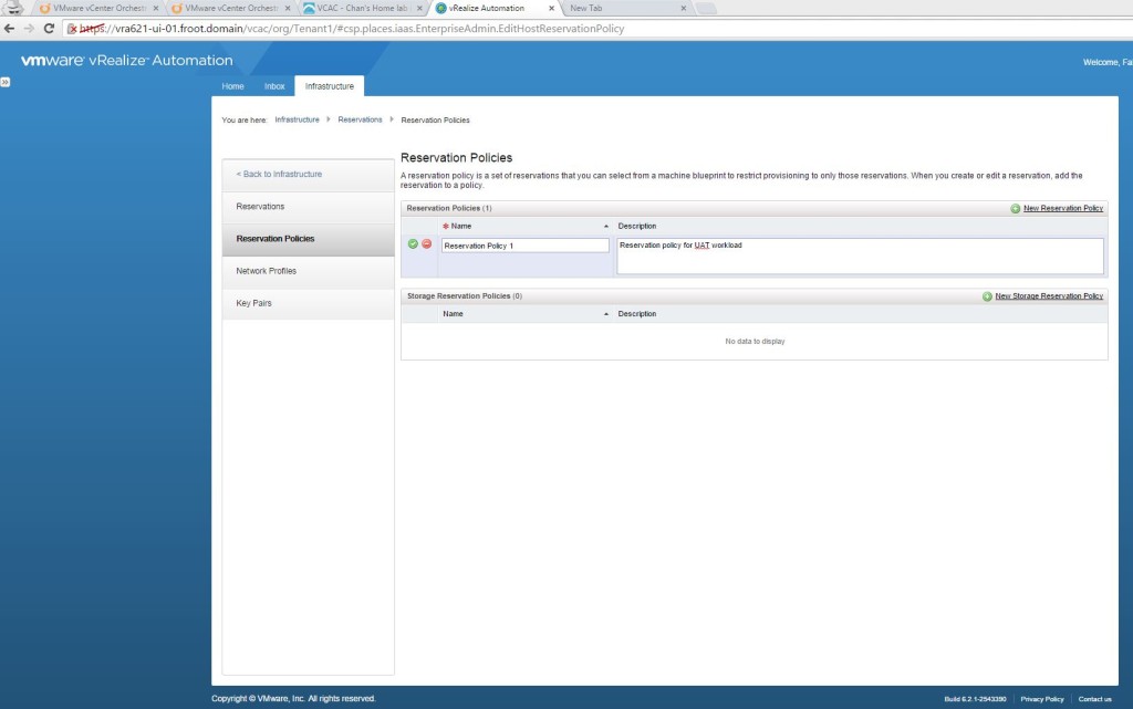
        3. Now amend the existing reservation “prodclust01-Res-1-UAT” (created above) to include this reservation policy 6.5.2.3
      3. Create Network Profiles
        1. Key points
          1. Network profiles allow machines to be assigned static IP addresses
        2. Create a network profile by going to Infrastructure->Reservations->Network Profile and selecting a new External network profile 6.5.3.2
        3. Define the IP range so that each machine provisioned by vRA will have an IP assigned from this range 6.5.3.3
      4. Modify the reservation profile to map the Network profile
        1. Go the reservation created above and under the network tab, select the Network Profile created. 6.5.4.1
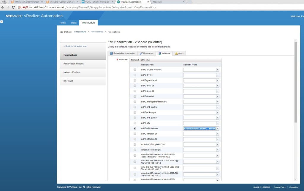
        2. Now, all VMs created in to this reservation will have an IP allocated using this IP range defined within the network profile.


There you go, we now have all the 3 main System-wide roles setup and their subsequent duties completed. Next up is the Tenant Administrators tasks which we’ll cover in a separate, dedicated post as the next logical step in our vRA deployment.


 Next: vRA Part 7 – Tenant Administrator & Basic Blueprints –>

VMware vRealize Automation Part 5 – vRO Deployment & Configuration & Integration

Next: vRA Part 6 – System / Infrastructure & Fabric Administrators –>

vRealize Orchestrator (was known as vCenter Orchestrator before) is an integral part of a vRA deployment as most of the vRA extensibility features relies on vRO being available and correctly integrated to vRA appliance & IaaS components. vRO in tern, connects to a number of other 3rd party systems through plugins, such as Microsoft Active Directory, Microsoft SQL, VMware vSphere, NSX….etc., where you can create a range of vRO workflows to carry out / automate tasks within these 3rd party systems. Due to the integration between vRA and vRO, these vRO workflows can be published within the vRA catalog and be made available via the built in self service portal (for example, you can publish a blueprint for resetting the passwords for an AD user through a workflow created on vRO).

I personally haven’t seen much documentation or clear guidelines with sufficient details on how to set up vRA with vRO for this level of extensibility which was one of the main reasons why I decided to publish this series of posts (which, hopefully will be addressed by VMware in the future).

So, now its the time to deploy the vRO and have it fully configured in preparation for the integration with vRA in due course. This article therefore looks at the deployment and the initial configuration of vRO component. (This should be considered a must have part of your vRA deployment)

vRO is available in many different forms

  • Available as a standalone appliance to be downloaded free of charge for vSphere customers
  • Automatically deployed if you install Windows version of vCenter (vRO Windows services are disabled by default though) – Note that this is now deprecated with the vRO 6.0.1 and hence SHOULD NOT be used going forward.
  • Available built in to the vRA itself (used for PaaS functions only, NOT used for IaaS functions for which you must register an external vRO)

In the interest of performance, and separation (and with the added ability of clustering should you need that in future), I prefer to deploy the standalone appliance (which is also the VMware’s recommended approach) so this article will rely on that. However, note that the post deployment configuration is still the same between the standalone appliance and the default version installed with vCenter.

The latest version of vRO released as of today, is the version 6.0.1, which was released in March 2015, in line with the announcement of vSphere 6.0. The release notes for the new version can be found here. It is compatible with vCenter server 4.1 and above.

Few highlights are below,

  • The stability of the vCenter Server plug-in has been improved by resolving major issues based on customer feedback (this was a real issue with earlier versions)
  • vRealize Orchestrator 6.0.1 supports the vSphere Web Client integration and context execution of vRealize Orchestrator workflows as part of vSphere Web Client 6.0
  • Switch Case introduced to handling conditional and branching operations within an automated workflow (If a value matches a switch case, specific workflow branch is executed)
  • Global error handling introduced
  • vRO control center beta introduced (Centralized admin interface for runtime execution, workflow monitoring & correlation with system resources, unified log access and configuration)

I will not be covering details about the Orchestrator itself, but only how to deploy & configure it within this post. If you need information about the vRO itself, including its architecture…etc. please refer to the official documentation found here.

Orchestrator Appliance Deployment

  1. Download the vRO appliance from My VMware portal as an ova and deploy on to the Management Cluster (NOT the compute / production cluster. Refer to the proposed architecture diagram in the previous post of this series here)
  2. During the deployment, you’d need to provide the information required and click next (ensure SSH is enabled) O3
  3. Once the appliance is deployed and powered on, SSH on to the appliance as root and change the root password expiry date.
    1. The password for the root account of the Orchestrator Appliance expires after 365 days. You can increase the expiry time for an account by logging in to the Orchestrator Appliance as root, and running passwd -x number_of_days name_of_account. o3.1
  4. Configure the appliance
    1. Go to the https://<vRO FQDN>:5480 and login using root.
    2. Change the Time Zone & Setup NTP (Admin->Time Settings)
    3. Update the Proxy settings should it be required and verify all other networking settings.

That’s it. the basic vRO appliance is now deployed and ready to be configured for vRO functionality which we’ll look at next.


vRO Configuration

  1. Login to the vRO appliance Configuration page 
    1. https://<vRO FQDN>:8283/vco-config (username: vmware)
  2. Bind the IP & DNS
    1. Click on Network on the left and select the IP address from the drop down menu to bind the vRO to the correct IP address.vRO2
  3. Import vCenter SSL Certificate
    1. Under Network, click on SSL Trust Manager tab and type import the vCenter server SSL certificate using the URL “https://<FQDN of the vCenter Server>” vRO3
    2. Note that this vCenter server should be the one managing the compute / production ESXi cluster, NOT the one managing the Management cluster.
  4. Setup Authentication Type
    1. Best practise recommendation is to configure the authentication source to be the vCenter SSO as this allows the user of vRO through vSphere web client. Note that the built in OpenLDAP is NOT recommended for production deployments.
    2. Import SSO server SSL certificate using the SSL Trust Manager
      1. Host: https://<FQDN of the SSO server>:7444 vRO4.2.1
    3. Setup vCenter SSO for authentication
      1. SSO Registration
        1. Select the Authentication mode as SSO Authentication within the Authentication section.
        2. Host: https://<FQDN of the SSO server>:7444
        3. Admin user name: Administrator@vsphere.local   vRO4.3.3
      2. SSO Configuration (Setup vRO admin group)
        1. Specify the SSO group that gets rights to the vRO server admin role here
        2. Select the SSO domain (I’m selecting the Active Directory attached to the SSO server)
        3. Select the dedicated Active Directory group (I’ve got a dedicated AD group created called “VMware vRO Administrators” which I’m going to add here.)   vRO 4.3.2.3
        4. Make sure the following accounts are members of this group on the AD
          1. vRA service account (<domain>\svc_vRA)
          2. vRO service account (<domain>\svc_vRO)
          3. Any domain user account requiring access to vRO workflows through vRO client.
        5. Note: One thing I’ve noticed here is that when changing this SSO Admin group (SSO or AD) always unregister the orchestrator and re-register with SSO. In the old version of vCO, it really didn’t like it when you just change this vRO admin group
  5. Assign vCenter license (default vRO license is only valid for 90 days)
    1. Under Licenses, select vCenter Server license
    2. Provide the vCenter address (<FQDN of the vCenter Server>) and an administrative user name to the vCenter (I’d create a new vRO service account, such as  <domain name>\svc_vRO, and assign vSphere administrative privileges to it and use it here as that’s neat and follow the RBAC guidelines) vRO5.2
    3. restart the vRO server service using the startup options
  6. Assign an external Microsoft SQL database
    1. The vRO 6.0.1 built in database is sufficient for small to medium scale deployments only and we will be using a separate SQL server as per VMware best practise.
    2. External database is also a pre-requisite for future clustering of the vRO.
    3. Prepare the SQL database
      1. Note: I’m going to use an external SQL 2008R2 server instance here.
      2. Verify that the protocol and port access is setup correctly on the SQL server vRO6.3.2
      3. Create an empty database on the SQL server (vRO601) vRO6.3.3.1
      4. Create a SQL user account (svc_vRO) and map this to the vRO601 database with dbo permission
        1. Note: With using the vRO Linux based appliance, I’ve had weird errors here and trying to get both Windows authenticationand SQL authentication work here. To cut a long story short, I only managed to get it to work after adding a Windows domain account (froot\svc_vRO) and a SQL account (svc_vRO), both with the same name added as DBO to the database. (makes no sense). This account will only be used by vRO to connect to its database. Ensure that SQL password expiry is ticked off when creating the sql account to avoid future problems. vRO6.3.4
    4. Import the SQL server SSL certificate to vRO using Trust Manager (Only applicable if the DB server uses SSL certs. Mine doesn’t so I will skip this)
    5. Setup the SQL server database connectivity
      1. Provide the SQL database connectivity information required and click apply changes vRO6.5.1
      2. Once prompted, create the database tables using the link provided. Once completed successfully, the status will be displayed. Click Apply Changes vRO6.5.2
  7. Assign a SSL Certificate to vRO
    1. Either create a self signed server certificate or import a certificate database (using an existing CA) vRO7.1.1
    2. Export the certificate DB for DR                                        vRO7.1.2
  8. Configure Orchestrator Plugins (Using vRO configuration interface)
    1. Configuration of Active Directory, SSH & vCenter Server plugins (all come installed by default in vRO) are now done through pre-defined workflows available within vCO rather than through the configuration interface
    2. Type the vRO admin username and password within the plugin section (When the Orchestrator server starts, the system uses these credentials to set up the plug-ins. The system checks the enabled plug-ins and performs any necessary internal installations such as package import, policy run, script launch, and so on) – I’m using the vRO domain service account (<domain>\svc_vRO) which is also a member of the vRO administrators group I’ve mapped under Authentication.
  9. Install new Orchestrator plugins
    1. Various addition vRO plugins can be downloaded from the vRO official web page (here) and installed on to the vRO via the configuration page so that vRO workflows can be created to integrate and manipulate external systems.
    2. Use the Install Application tab within the General section of the vRO configurator to install plugins that have a .vmoapp extension.
    3. There are a number of additional plugins available here but I will be installing the followings, for the purpose of this article
      1. Install the plugin VMware vCenter Orchestrator Plugin for NSX 1.0.1 – Required for vRO workflow creation for NSX in order to orchestrate some NSX tasks
        1. Compatibility: Based on the VMware product Interoperability Matrix as of now, for vRO 6.0.1, NSX version 6.1, 6.1.1 & 6.1.2 are the only versions of NSX supported and that requires the vRO NSX plugin version 1.0.1. But the vcoteam.info (official site for vRO team) site’s plugin list only contains the NSX 1.0.0 plugin and not version 1.0.1. So be sure to download the correct version via the link I’ve provided above.
        2. Note: This plugin is required for vRO workflow creation for NSX in order to orchestrate some NSX tasks. The current workflows included within this package are limited however and the installation of the NSX-v Dynamic Types plugin V2 (below) will add additional NSX related workflows. Once these workflows are available, they can be leveraged by vRA.
        3. Install the NSX plugin (using o11nplugin-nsx-1.0.1.vmoapp file) vRO9.2.1.2
        4. Accept license & Apply changes                                            vRO9.2.1.3
        5. Restart vRO server to take effect (note that the plugin status may not change to “installed” immediately after the vCO service restart. This can take some time)   vRO9.2.1.4
        6. Login to the vRO client and verify the NSX workflows are now available within Library->NSX folder vRO9.2.1.5
      2. Install the plugin NSX-v Dynamic Types plug-in V2
        1. Note: A handy NSX Dynamic Types plugin to use with vRA Advanced Service Designer. This plug-in can be customized and extended using the plug-in generator V2 package.
        2.  Install instructions are all available in the link above (summary below)
          1. Rename the downloaded package com.vmware.coe.plugin.dynamictypes.nsx.v2.package
          2. Import the package (Using vRO client, NOT the configuration page)
          3. Verify that the package and the additional NSX workflows now appear within the vRO client. vRO 9.2.3
          4. More steps are required to be carried out to complete this which will be done under step 10 below
      3. Install the plugin VMware vRealize Orchestrator vRA Plug-in 6.2.0
        1. Note: This is required for integration with vRA 6.2.
        2. Install the vRA 6.2.x plugin using the o11nplugin-vcac-6.2.0-2287231.vmoapp on the vRO configuration page vRO9.3.1
        3. Verify the installation and restart the vCO service (note that the plugin status may not change to “installed” immediately after the vCO service restart. This can take some time)                                                                                                                                                            vRO9.3.2
        4. Note: Login to the vRO client and ensure all default workflows are visible within the client. (I’ve had repeated issues whereby, after the vRA 6.2 plugin has been installed, all default plugins and their workflows disappeared within vCO. If this happens, within the vRO configuration page, go to Troubleshooting section and click “Reset current version” under “Reinstall the plug-ins when the server starts and reboot the vRO appliance) – This can potentially save you lots of time….!!
  10. Configure Orchestrator Plugins (using vRO workflows) – We will configure the key plugins here and leave some to be configured later
    1. Configure vCenter plugin
      1. Note: The way to integrate vCenter server may differ depending on whether you have vCenter 5.5 or 6.0 as well as whether its a windows install or the vCSA. In my case, its vCenter 5.5 on good old Windows so the below steps are based on that configuration.
      2. Login to the vRO client (you can download the client installable from https://<vRO FQDN>:8281 or launch the client directly from there)  and run the workflow Library-> vCenter->Configuration->Add a vCenter server instance   10.1.2
      3. Now, select whether you are happy to use a shared session for vRO to connect to vCenter server. If you using a shared session (meaning, you’ve answered “No”), provide the credentials that the vRO uses to connect to the vCenter with (shared credentials for all users). I’m using the vRO service account (svc_vRO) which I’ve made an Administrators on the vCenter instance. This is usually good enough as I can see all vRO driven activities on the vCenter logs / events clearly thanks to the service account name.  Also, since the ultimate goal is to call these workflows via vRA portal, and when I specify blueprints based on these workflows, I’m already controlling who has access to access those blueprints, so the shared credentials between vRO and vCenter is the best option. If however you decides to not use shared credentials, you need ensure each user who access vCO workflows though vRA catalog, will have sufficient permission on vCenter to execute that specific workload and I don’t think that is a good way to go about it, architecturally.     10.1.3
      4. Once the workflow has been successfully run, you’ll see the message on the screen as follows. 10.1.4
    2. Register vCenter Orchestrator as a vCenter Server Extension
      1. Note: This important so that vRO workflows will automatically be available within the vSphere Web Client to execute.
      2. Login to vRO client and rung the workflow: Library -> vCenter -> Configuration -> Register vCenter Orchestrator as a vCenter Server Extension
      3. Select the vCenter server (managing compute & edge cluster that the above workflow was run against) here. 10.2.2
      4. Verify it ran successfully
      5. Verify on the Managed Object Browser for that vCenter that the vRO extension is listed correctly. Instructions are as follows
        1. In a Web browser navigate to the managed object browser of your vCenter Server instance. https://<vcenter_server_ip?/mob
        2. Log in with vCenter Server credentials.
        3. Under Properties, click content.
        4. On the Data Object Type: ServiceContent page, under Properties, click ExtensionManager.
        5. On the Managed Object Type page, under Properties, click the Orchestrator extension string.extensionList[“com.vmware.vco”]. The extension has a server property which contains an array of type ExtensionServerInfo. The array should contain an instance of the ExtensionServerInfo type with a url property which contains the URL of the registered Orchestrator server.
        6. On the Data Object Type: Extension page, under Properties, click server. You can see information about the Orchestrator server registered as an extension, such as serverThumbprint and url. The serverThumbprint property is the SHA-1 thumbprint of the Orchestrator server certificate, which is a unique identifier of the Orchestrator server. The url property is the service URL of the Orchestrator server. There is one record per IP address. If the Orchestrator server has two IP addresses, both of them are displayed as service URLs.        10.2.4.6
    3. Configure the Active Directory Plugin
      1. Login to the vRO client and run the workflow: Library->Microsoft->Configuration->Configure Active Directory Server
      2. Provide the answers including the AD dc name (I’d providing the root of the domain address which is automatically directed to any of the DCs in the domain rather than pointing at a single DC.                                      AD 10.3.1
      3.      Now select the authentication method to the AD as a shared session. If a shared session is not used, the user who runs the vRO workflow is expected to have sufficient rights in the AD to run the particular workflow which WILL NOT be practical once the vRO is integrated with vRA and users start requesting machine provisioning from blueprints which in turn, calls for vRO workflows. AD-1
    4. Configure VMware vRealize Orchestrator vRA Plug-in 6.2.0 – This step is key….!!
      1. Add vRA Host
        1. Import the vRA server SSL certificate
          1. Run the workflow “Import a certification from URL” under library->configuration->SSL Trust Manager
          2. Provide the vRA appliance details in the URL & Submit. Verify Its run correctly. vRA 10.4.1.1.2
        2. Add the vRA host
          1. Run “Add a CAC host” workflow under vCAC->Configuration and select the vRA server FQDN and the URL (with https://) vRA 10.4.1.2.1
          2. Use the shared session option using the Administrator@vsphere.local account to connect to the vRA server vRA 10.4.1.2.2
          3. Verify its run successfully at the end.
      2. Add the vRA IaaS host
        1. Setup Infrastructure Administrators Group on the default tenant
          1. Login to the vRA UI using https://<vRA Appliance FQDN>/shell-ui-app using the Administrator@vsphere.local account IaaS 0
          2. Go to the Administratprs tab within the vSphere.local tenant (default) and add an appropriate AD group for vRA Infrastructure Administrators (I have a group created here called <domain>\VMware vCAC Inf Admins and a user account named <domain>\inf-admin as a member of that group) IaaS 0 1
        2. Run “Add a vCAC IAAS host” workflow
          1. Run the workflow “Add a vCAC IAAS host” under vCAC->Configuration and select the vRA server (already added to vRO) IaaS 1
          2. Host name is are auto populated. Change this to be the name of your IaaS windows server (as shown below) and Click next.                        IaaS 2
          3. My preference is to use the shared session option here. The shared user account used to connect to the IaaS windows server needs to be a administrative account that has local administrative rights to the IaaS server where the model manager database is installed. As such, I’m going to use the vRA service account (domain service account that was created and used to install the IaaS services with during an earlier step here which had admin rights to the IaaS server).  DO NOT type the domain name here. Just type the account name as the domain is provided in the next step.      IaaS 3
          4. Change the domain name to the appropriate domain name and submit.   IaaS 2.5
          5. Verify it runs successfully.
      3. Install vRO Stub Workflow Customization
        1. Note: This workflow will modify the default Workflow Stubs used by vRA so that vRO workflows can be called during normal vRA driven machine provisioning & disposing to achieve e significant level of customisability.
        2. Run the vCloud Automation Center->Infrastructure Administration->Extensibility->Installation->Install VCO Customisation  IaaS 4
        3. Verify that the defaults Stub Workflows are now modified using vRA Designer
          1. Download the vRA Designer from using the URL https://<vRA appliance FQDN>:5480 and under vRA Settings tabIaaS 5
          2. Install the vRA Designer (model manager runs on the IaaS server. In my case, its the first IaaS server deployed. Ensure you use the FQDN for the server name here)                              IaaS 6
          3. Launch the vCAC Designer application installed above               IaaS 7
          4. Click on Load button at the top to load the internal vRA workflow configuration to see the updated version numbers of the built in workflows IaaS 8
      4. Due to this customization, it provides the ability to call vRO workflows during provisioning process using vRA IaaS Blueprints. To assign these vRO workflows to each Blueprint (to be invoked during provisioning stage), we’ll need to later run the Library->vCAC->Inf Administration->Extensibility->Assign state change workflow and select the required Blueprint. – We will be using this extensibility feature later on, but so far we’ve just had all the preparation work completed.

There you have it. vRO 6.0.1 is now deployed, its integrated with AD, vCenter and vRA and the vRA’s default provisioning stub workflows have also been modified so that we can call vRO workflows during vRA IaaS machine provisioning process and use custom properties to populate the input parameters being required by those vRO workflows.

Now that we have all the pre-requisites for a fairly complete vRA deployment, we’ll next look at the initial vRA setup and all the different user accounts involved.

Cheers

Chan

 Next: vRA Part 6 – System / Infrastructure & Fabric Administrators –>

NSX 6.1.2 Bug – DLR interface communication issues & How to troubleshoot using net-vdr command

I have NSX 6.1.2 deployed on vSphere 5.5 and wanted to share the details of a specific bug applicable to this version of NSX that I came across, especially since it doesn’t have a relevant KB article published for it.

After setting up the NSX manager and all the host preparations including VXLAN prep, I had deployed a number of DLR instances, each with multiple internal interfaces and an uplink interface which in tern, was connected to an Edge Gateway instance for external connectivity. And I kept on getting communication issues between certain interfaces of the DLR, where by for example, the internal interfaces connected to vNIC 1 & 2 would communicate with one another (I can ping from a VM on VXLAN 1 attached to the internal interface on vNIC 1 to a VM on VXLAN 2 attached to the internal interface on vNIC 2) but none of them would talk to the internal interface 3, attached to the DLR vNic 3 or even uplink interface on vNic 0 (Cannot ping the Edge gateway). The interfaces that cannot communicate were completely random however and was persistent on multiple DLR instances deployed. All of them had one thing in common which was that no internal interface would talk to the uplink interface IP (of the Edge gateway attached to the other end of the uplink interface).

One symptom of the issue was what was described in this blog post I posed on the VMware communities page, at https://communities.vmware.com/thread/505542

Finally I had to log a call with NSX support at VMware GSS and according to their diagnosis, it turned out to be an inconsistency issue with the netcpa daemon running on the ESXi hosts and its communication with the NSX controllers. (FYI – netcpa gets deployed during the NSX host preparation stage, as a part of the User World Agents and is responsible for communication between DLR and the NSX controllers as well as the VXLAN and NSX controllers- see the diagram here)

During the troubleshooting, it transpired that some details (such as VXLAN details) were out of sync between the hosts and the controllers (different from what was shown as the VXLAN & VNI configuration in the GUI) and the temporary fix was to stop and start the netcpa daemon on each of the hosts in the compute & edge cluster ESXi nodes (commands “/etc/init.d/netcpad stop” followed up by “/etc/init.d/netcpad start” on the ESXi shell as root).

Having analysed the logs thereafter, VMware GSS confirmed that this was indeed an internally known issue with NSX 6.1.2. Their message was “This happens due to a problem in the tcp connection handshake between netcpa and the manager once the last one is rebooted (one of the ACKs is not received by netcpa, and it does not retry the connection). This fix added re-connect for every 5 seconds until the ACK is received“. Unfortunately, there’s no published KB article out (as of now) for this issue which doesn’t help much. expecially if you deploying this in a lab…etc.

This issue has (allegedly) been resolved in NSX version 6.1.3 even thought its not explicitly stated within the release notes as of yet (the support engineer I dealt with mentioned that he’s requested this to be added)

So, if you have similar issues with NSX 6.1.2 (or lower possibly), this may well be the way to go about it.

One thing I did lean during the troubleshooting process (which was probably the most important thing that came out of this whole issue for me, personally) was the understanding of the importance of the net-vdr command, which I should emphasize here though. Currently, there are no other ways to check if the agents running on the ESXi hosts have the correct configuration settings to do with NSX other than looking at it on command line…. I mean, you can force a resync of the appliance configuration or redeploy the appliances themselves using NSX GUI but that doesn’t necessarily update the ESXi agents and was of no help in my case mentioned above.

net-vdr command lets you perform a number of useful operations relating to DLR, from basic operations such as adding / deleting a new VDR (Distributed Router) instance, dumpi9ng the instance info, configure DRl settings including changing the controller details, adding / deleting DLR route details, listing all DLR instances, ARP operations such as show, add & delete ARP entries in the DLR & DLR Bridge operations and has turned out to be real handy for me to do various troubleshooting & verification operations regarding DLR settings. Unfortunately, there don’t appear to be much documentation on this command and its use, not on the VMware NSX documentation NOR within the vSphere documentation, at least as of yet, hence why I thought I’d mention it here.

Given below is an output of the commands usage,

net-vdr

So, couple of examples….

If you want to list all the DLR instances deployed and their internal names, net-vdr –instance -l will list out all the DLR instances as how ESXi sees them.

net-vdr --instance -l

If you NSX GUI says that you have 4 VNI’s 5000, 5001, 5002 & 5003 defined and you need to check whether if all 4 VNI configurations are also present on the ESXi hosts, net-vdr -L -l default+edge-XX (where XX is the unique number assigned to each of your DLR) will show you all the DLR interface configuration, as how the ESXi host sees it.

net-vdr -L l

If you want to see the ARP information within each DLR,  net-vdr –nbr -l default+edge-XX (where XX is the unique number assigned to each DLR) will show you the ARP info.

net-vdr --nbr -l default+edge-XX


Hope this would be of some use to those early adaptors of NSX out there….

Cheers

Chan


VMware vRealize Automation Part 4 – IaaS Server Deployment

Next: vRA Part 5 – vRO Deployment & Configuration & Integration –>

IaaS server is installed separately on a Windows server and is a key part of a vRealize Automation deployment. IaaS is the part within vRA that enables the rapid modelling and provisioning of servers & desktops across virtual and physical, private and public or Hybrid cloud infrastructures. Without the IaaS components, a vRA deployment is pretty none existent and in my view, pretty useless.

IaaS Component Architecture

IaaS components included within the vRA are as follows

  • IaaS Web site:
    • The IaaS Web site component provides the infrastructure administration and service authoring capabilities to the vCloud Automation Center console
    • Gets the updates from the Model manager for DEM, Proxy agents and the SQL database
  • Model Manager:
    • Provides updates from the DEM, proxy agents, and database to the IaaS web site.
    • The Model Manager holds the core of the business logic for vRA.
    • This business logic contains all the information required for connecting to external systems like VMware vSphere, Microsoft System Center Virtual Machine Manager, and Cisco UCS Manager…etc.
    • The Model Manager Web service component can have multiple instances and communicates with a Microsoft SQL database.
  • Manager Service
    • The Manager service coordinates communication between DEMS, agents, and the database.
    • The Manager Service communicates with the console Web site through the Model Manager. This service requires administrative privileges to run on the IaaS server
  • Distributed Execution Managers (DEMs)
    • DEMs execute the business logic of a vCloud Automation Center model, interacts with external systems, and manages virtual, cloud, and physical machine resources
    • DEMs are used for provisioning and managing machines on vCloud Director, vCloud Air Service, Red Hat Enterprise Virtualization Manager, Microsoft System Center Virtual Machine Manager, Amazon Web Services, Physical Server Management Interfaces for Dell, HP, and Cisco.
    • Runs as a Windows Service (1 service for DEM Orchestrator and another for DEM Worker
  • SQL Database
    • The IaaS component of vRealize Automation uses a Microsoft SQL Server database to maintain information about the machines it manages and its own elements and policies
    • A system administrator need to manually create the database during installation
  • Agents
    • Hypervisor proxy agents: Provisioning and managing machines and services on vSphere, Citrix, XenServer, Hyper-V. They send commands to and collect data from vSphere ESX Server, XenServer, and Hyper-V virtualization hosts and the virtual machines provisioned on them
    • EPI Agents: External provisioning infrastructure PowerShell agents
    • VDI Agents: Virtual Desktop Infrastructures PowerShell agents for XenDesktop Delivery Controller and VMware View Horizon enabling the XenDesktop web interface access through vRA
    • WMI Agents: Windows Management Instrumentation agents enhances the ability to monitor and control system information and allows you to manage remote servers from a central location. It enables the collection of data from Windows machines that vRealize Automation manages.
    • Management Agents: Management Agents collect support and telemetry information and registers IaaS nodes. A Management Agent is installed automatically on each IaaS node.
    • Each agent runs as a Windows service

One thing I’ve noticed on most of the VMware documentation is a lack of clarity in the form of a diagram of how these components interact. I’ve therefore attempted to document this as below.

1. Components


IaaS Server Deployment

The deployment of the IaaS component is not the easiest of the tasks and is somewhat unlike the typical user friendly deployment style we are used to with other VMware products (guessing this was because it came from the Dynamic Ops acquisition rather than being developed in house by VMware). It could be a quite a tedious task to ensure that all the various pre-requisites are in place on the IaaS Windows server manually and then having to run the setup (which is also a little cumbersome). Fortunately, a VMware TME (Brian Graf) has put together a really handy PowerShell script to automate the pre-requisite setup which I’ve used few times in the past and it has saved me lots of time. We’d be using that here.

Here are the steps involved in deploying the IaaS server components, starting from the Pre-requisites

  1. Ensure the Pre-requisites are in place on the IaaS server
    1. Build a Windows 2008 R2 / Windows 2012 / Windows 2012 R2 server
    2. Create a Domain account as the vRA service account. Lets call it <DomainName>\svc_vRA.
    3. Login to the Windows server (VM) and ensure that the vRA service account is a member of the local Administrators group 1.3
    4. Download the vRA 6.2 pre-req checker PowerShell script from GitHub and copy locally.
    5. Login as the vRA service account Run the “vRA 6.2 PreReq Automation Script.PS1” and follow the guided install wizard to add / download the additional components as required and install them automatically.   1.5
  2. Ensure the pre-requisites are in place on the SQL server
    1. Grant the vRA service account (svc_vRA) sysadmin rights on the SQL server instance (This is only temporary and is required during the installation period only for the installer to automatically create the database required which can later be revoked.2.1
  3. Verify the Pre-Requisites are correctly installed & configured on the IaaS server
    1. login to the IaaS server as the vRA service account.
    2. Download the IaaS installer specific to your vRA deployment by logging in to the https://<FQDN of the vRA Appliance>:5480 (login using root) 3.2
    3. Login to the installer using root and password specified during the deployment of the vRA appliance 3.3
    4. As this is the first IaaS server, I will be installing all the roles on this server (Will add a secondary DEM Orchestrator and DEM worker to another server later). Therefore select Complete Install and click next 3.4
    5. The built-in Pre-Requisite checker will now verify that you’ve got all the pre-requisites and confirm. 3.5
    6. If there are warnings against the Windows Firewall (even if its disabled), ensure that the Distributed Transaction Coordinator is allowed through the firewall and once verified, select the Firewall related warnings and click bypass. 3.6
    7. Move on to the next step
  4. Install the IaaS components
    1. From the Step 3.7 above, click next to proceed with the installation
    2. Provide the followings to the installer
      1. vRA service account username
      2. vRA service account password
      3. Passphrase (is a series of words that generates the encryption key used to secure database data and would required if the DB is to be restored)
      4. SQL server name (DO NOT type the instance name if there’s only a singly instance on the server. Just use the SQL server FQDN)
      5. vRA Database name & Click Next 4.2
    3. Provide the DEM and Agent names and click next 4.3
    4. Under the Component Registry,
      1. Provide the FQDN of the vRA appliance
      2. Load the default Tenant
      3. Download the certificate using the button & accept using the check box
      4. Provide the default SSO Administrator credentials (Administrator@sphere.local if using the vCenter SSO) & click test to verify. Verify the IaaS server name & Click next 4.4
    5. Click Install to begin the installation. Install log would be at “C:\Program Files (x86)\VMware\vCAC\InstallLogs\” folder.    4.5
    6. Once the installation complete (can take around 20 mins), click next & finish
  5. Verify the IaaS installation & Service registration
    1. Now login to the https://<FQDN of the vRA Appliance>:5480 as root and ensure the IaaS-service has a status as REGISTERED5.1
    2. Also verify that you can see the Infrastructure Administrators section being enabled within the Login to vRA UI for the default tenant (URL “https://<FQDN of the vRA Appliance>/shell-ui-app) when you login with the default SSO administrator credentials (Administrator@vsphere.local). Note that this was previously disabled pending the installation of the IaaS components. 5.2
  6. Revoke the temporary SQL permissions
    1. SysAdmin privileges assigned to the vRA service account on the SQL server instance is no longer required, (verify that the account has automatically been given the DBO permission to the vRA database) so you can now revoke this permission on the SQL server.6


That is it. The vRA IaaS server components have now been set up successfully. Next, we’ll look at deploying & configuring the latest version of vRO (vRealize Orchestrator – 6.0.1) which is a critical part of a useable vRA deployment.

Cheers

Chan

Next: vRA Part 5 – vRO Deployment & Configuration & Integration –>

VMware vRealize Automation Part 3 – vRA Appliance Deployment

Next: vRA Part 4 – IaaS Server Deployment –>

Ok, now that we’ve established the need for a dedicated management cluster to host the vRA management components, lets look at the deployement highlights of the vRA components within the management cluster.

  1. vRA Identity Appliance:
    1. If you want to use the vRA’s own identity management appliance, that should be the first component to be deployed. Deployment of this appliance is pretty straight forward and is self explanatory, hence I will not be covering here. However I will instead be using the vSphere SSO as the identity management source for vRA environment also, in order to keep all authentication for the my virtual infrastructure centralised (and simple).
    2. But if you are NOT planning on using vSphere SSO, make sure you download the vRA identity appliance from VMware and deploy on to the management cluster.
    3. Once deployed, ensure to configure the time zone and the NTP server settings using the management IP (specified during the Appliance deployment)
  2. vRA Appliance deployment
    1. Download the vRA appliance from VMware. Documentation for the latest release can be found here
    2. Deploy the appliance on to the Management Cluster using the vCenter server that manages it. You would need the following information during the deployment 1
  3. Configure the vRA Appliance
    1. Once the appliance deployment is complete, use the URL https://<FQDN/IP of the vRA appliance>:5480 to access the management interface
    2. Login with username root and password as specified during the deployment
    3. Set up the Time Zone (System->Time Zone)
    4. Set up the Host name (Network->Address) & Proxy server (Network->Proxy) if applicable
    5. Set up NTP to sync time (Admin->Time Settings)
    6. Set up the vRA specific settings
      1. Setup SSL (vRA Settings->Host Settings) – You can either self generate a Certificate or import a certificate obtained from a CA    2. SSL
      2. Set up SSO (vRA Settings->SSO) – You can connect to default vRA identity appliance or the vSphere SSO (>5.5 1b) as below using default SSO admin account. Note the following key points regarding the SSO host name
        1. Important Note: If you have an existing vRA / vCAC deployment already that is using a vSphere SSO server, note that you CANNOT use the same SSO server for another vRA server. I had number of issues when I attempted this, and the most notable one 1 where the non of the group / roles created within the default tenant (such as infrastructure admin & tenant Admin) would work and may come up with “401 – Unauthorized: Access is denied due to invalid credentials” error when logged in. This doesn’t appear to be correctly documented so watch out, but shouldn’t apply to most as its unlikely that you’d have multiple vRA deployments in the same organisation. the only way around this (if you have to use the same SSO source for multiple vRA’s) is to create a tenant rather than using the default tenant. Note the tenant name should be unique within the whole SSO too (if you have Tenant-A in vRA-A, you cannot add another Tenant-A on vRA-B using the same SSO)
        2. Host Name: When using the vSphere SSO server, host name should have the same case as what’s been registered in the vCenter SSO (if unsure, browse to https://ssoserver:7444/websso/SAML2/Metadata/vsphere.local and save the vsphere.download file when prompted.  Open the vsphere.download file in notepad or some text editor.  Locate the entityID attribute of the EntityDescriptor element.  Use the SSO server name in the way its specified here paying attention to the case)
        3. Port: 7444 in the host name for the vCenter SSO is NOT required with the vRA6.2.1 (this was required to be specifically specified in the host name field with the earlier versions of vCAC)
          3. SSO
      3. Add the appropriate license.(vRA Settings->License). It should be noted here that the license key added here should be the vRA standard or vRA Adavnced and not the vCloud suite license.
      4. Database connectivity (vRA Settings->Database) can be ignored in most cases unless you want to connect to an external Postgre SQL server / cluster
      5. Messaging (vRA Settings->Messaging) can also be ignored as this should have been automatically configured.
      6. Cluster configuration (vRA Settings->Cluster) can be bypassed unless you are creating a vRA appliance cluster in which case you can join an existing cluster here.
      7. Once all above are configured, allow couple of minutes and ensure all vRA services are now registered within the “Services” tab. 4. Services
    7. Configure the Identity stores
      1. Here, you can create new tenants (for a multi tenant deployment) or use the default tenant (automatically created). I’m going to use the default tenant here.
      2. Login to vRA UI using the URL “https://<FQDN of the vRA Appliance>/shell-ui-app” with the default SSO administrator credentials (Administrator@vsphere.local). The default vSphere.local tenant should be available. 5. Login
      3. Click on the vSphere.local, go to Identity stores and verify the default domain name listed (by default, the native ad domain would have been added here)
      4. If you need a separate identity / authentication realm (AD or open LDAP supported), you add it here
    8. Setup Tenant Administrators for the tenants
      1. Login with the SSO Administrator account and click on the tenant and then go to Administrators (using the default tenant in the example below)
      2. Add the AD user account or group to be used as the Tenant Administrator 7. Tenant admin 2
    9. Add the inbound and outbound email servers within the Email Servers tab on the left
    10. (Optional) Set up branding for the vRA user interface if required using the Branding tab


That’s it, the vRA appliance is not set up and the Tenant Admin account is also setup. Next up would be the IAAS server installation.


Next: vRA Part 4 – IaaS Server Deployment –>

VMware vRealize Automation part 2 – Deployment Architecture – Dedicated Management Cluster

Next: vRA Part 3 – vRA Appliance Deployment –>

Having had a look at the vRA support matrix, next point to consider in a typical vRA deployment is the deployment architecture which I’ll briefly explain below

vRA is part of the VMware product set that recommends the use of a dedicated management cluster (along with vCD and NSX). This is important because the concept behind this is that a dedicated management cluster will isolate all the VM’s that make up the management infrastructure such as Active Directory VMs, vCenter & SQL server VMs, Monitoring VMs…etc. This separation provides a separate execution context from those virtual machines that provides end user accessible resources, in other words, compute VM’s / production VMs that actually run the business critical workloads. Such a separation inherently provide a number of benefits to an enterprise.

  • Security & isolation of management workloads
  • Elimination of resource (and otherwise) contention between management & production workloads.
  • DR and Business Continuity without replicating un-necessary management components

An example would look like below

1.0 Mgmt cluster

Within a typical vRA deployment, the management cluster would host the following vRA components

  • vRA UI appliance (if using a distributed high availability deployment model, the vRA appliance cluster, Postgre SQL cluster & load balancers)
  • vRA Identity appliance (of is using the vSphere SSO, vSphere SSO server/s)
  • IAAS windows VMs (if using a distributed high availability deployment model, IAAS web servers, Model Manager web servers, MS SQL DB cluster, DEM Orchestrators, DEM Workers & Agents and the required load balancers)
  • vRO appliance (if using a distributed high availability deployment model, vRO cluster and the backend SQL DB cluster with relevant load balancers)

During the configuration of IAAS components, vRA will connect to various end points (such as a vCenter server instance that manages a number of resource clusters) and once an endpoint such as a vCenter instance is connected, a Fabric Administrator would create resource reservations for each cluster managed by that vCenter instance. Once these reservations are created, vRA typically assumes complete control over those clusters (resource reservations within the clusters) to be able to use those resource reservations as how it sees fit. This could present problems if you run your management infrastructure VMs (such as vCenter server and vRA appliances..etc.) in one of those same clusters as vRA will not take in to account the existence of other VMs in the same cluster, that was not created by itself. This could result in vRA deploying VM’s (based on IAAS request from users) which will affect the resources available for the management VMs with a  potential to affect performance of both the management VMs and production VMs (created by the vRA based on blueprints). It is therefore typically recommended that you keep all resource / compute clusters separate from the vRA management VMs and under the full control of vRA itself (no manual creation of VM’s in the resource clusters).

If you have an existing vCloud Director deployment or an NSX deployment, you may already have a dedicated management ESXi cluster in place as these products makes it a mandatory requirement to have one. However even if you don’t and are considering a vRA deployment, I would highly encourage you to have a dedicated management cluster to host the vRA infrastructure components.

An example high level design where vRA along with VMware NSX is deployed using a Management cluster could look like below.

2.0 HLD arhcitecture


Next: vRA Part 3 – vRA Appliance Deployment –>

VMware vRealize Automation Part 1 – vRA Support Matrix

Next: vRA part 2 – Deployment Architecture – Dedicated Management Cluster –>

The first step that should be involved in deploying vRealize Automation in any one’s book is to refer to the support matrix PDF on VMware web site. There are a strict number of support limitations which you must be aware of, and all the key information you need can be found within this document.

I’d encourage you to read the document for complete support details (and stay up to date with newer versions too) but given below is a high level summary of some key contents (based on the current vRA release of 6.2.1).

  • vRA IAAS server
    • Host OS (for IAAS components) – W2k8R2, W2k12 & W2k12R2 only (note that Windows 2008 is NOT supported)
    • IAAS DB: SQL 2008 R2 SP3 or higher (up to SQL 2014)
    • Web Server (for IAAS model manager…etc.): IIS 2008 R2 & IIS 2012 only


  • vRA Appliance
    • DB Support: vPostgres Appliance 9.2.4 / 9.2.9.x / 9.3.5.x, PostgreSQL 9.2.4 / 9.2.6 / 9.3.4
    • SSO / Authentication sources: vRA Identity Appliance v6.2, vSpere SSO 5.5 1b or above (up to PSC 1.0 with vSphere 6.0)


  • Hypervisor Support (for the vRA Hypervisor proxy agent):
    • VMware: ESX 4.1 to U2, ESX 4.1 to U2, ESXi 5.0 onwards (including ESXi 6.0) – note that Application Director only works with vSphere and NOT other hypervisors
    • Red Hat: KVM RHEN 3.1 only
    • Microsoft: Hyper-V 2008 R2 SP1 onwards (inc 2012 R2)
    • Citrix: XenServer 5.6 through to SP2, 6.0.2 & 6.2 through to SP1


  • Hypervisor management platform support (for vRA proxy agent and DEM worker compatibility)
    • VMware: vCenter 4.1 through to U2, vCenter 5.0 U3 onwards (till vCenter 6.0)
    • Microsoft: SCVMM 2012 (Hyper-V) only
    • Red Hat: RHEV-Manager 3.1 / 3.3


  • Network Virtualisation support
    • VMware vCNS 5.5.3 only, NSX 6.1 and above (up to 6.1.3)


  • Cloud Support (IAAS Endpoint compatibility)
    • VMware: vCD 5.1.x & 5.5.x, vCloud Air
    • Amazon: AWS
    • (Note that Azure is NOT support as a cloud endpoint)


  • Image Deployment Methods (IAAS)
    • Microsoft: SCCM 2012 & SCVMM 2012 only, Windows WinPE & WIM imaging
    • NetApp: FlexClone on Data OnTap 7.3.1.1, 8.0.1 & 8.1 (Note that this doesn’t state whether its cDOT or 7Mode. Also, the most latest OnTap version 8.3 is NOT supported yet)
    • BMC: Blade Logic Operations Manager 7.6 & 8.2
    • HP: Software Server Automation 7.7
    • Citrix: Provisioning Server 6.0 & 6.1
    • Linux: Red Hat Linux kickstart, SUSE AutoYaST
    • PXE boot


  • Guest OS
    • Microsoft: Windows 7, 8, 8.1, W2K8R2, W2K12 & W2K12R2
    • Red Hat: RHEL 5.9, 5.10, 6.1, 6.4, 6.5, 7.0
    • SUZE: SLES 11 SP2 & SP3
    • CentOS: CentOS 5.10, 6.4. 6.5, 7.0
    • Debian: 6 & 7.0
    • Ubuntu: 12.04 LTS & 13.10
    • Oracle: Oracle Enterprise Linux
    • VMware: ESX/i 4.1 U2, ESXi 5.1 and above (up to ESXi 6.0)


  • VDI Connection Broker support
    • Citrix: XenDesktop 5.5 and above (up to 7.6.x)
    • VMware: Horizon View 6.x only


  • Task Automation Engines / Scripting support
    • VMware: vCO 5.5.1 and above (up to vRO 6.0)
    • Microsoft: PowerShell 2.0


Next: vRA part 2 – Deployment Architecture – Dedicated Management Cluster –>

7. NSX L2 Bridging

Next Article: ->

NSX L2 bridging is used to bridge a VXLAN to a VLAN to enable direct Ethernet connectivity between VMs in a logical switch, or a distributed dvPG (or between VMs and physical devices through an uplink to the external physical network). This provides direct L2 connectivity rather than L3 routed connectivity which could have been achieved via attaching the VXLAN network on to an internal interface of the DLR and also attaching the VLAN tagged port  group to another interface to route traffic. While the use cases of this may be limited, it can be handy during P2V migrations where direct L2 access from the physical network to the VM network is required. 0 Overview Given below are some key points to note during design.

  • L2 bridging is enabled in a DLR using the “Bridging” tab (DLR is a pre-requisite)
  • Only VXLAN and VLAN bridging is supported (no VLAN & VLAN or VXLAN & VXLAN bridging)
  • All participants of the VXLAN and VLAN bridge must be in the same datacentre
  • Once configured on the DLR, the actual bridging takes place on the specific ESXi server, designated as the bridge instance (usually the host where DLR control VM runs).
  • If the ESXi host acting as the bridge instance fails, NSX controller will move the role to a different server and pushes a copy of the MAC table to the new bridge instance to keep it synchronised.
  • L2 bridging and distributed routing cannot be enabled on the same logic switch at present (meaning, the VMs attached to the logical switch cannot use the DLR as the default gateway)
  • Bridge instances are limited to the throughput of a single ESXi server.
    • Since, for each bridge, the bridging happens in a single ESXi server, all the related traffic are hair-pinned to that server
    • Therefore, if deploying multiple bridges, its better to use multiple DLR’s where the control VM’s are spread across multiple ESXi servers to get aggregate throughput from multiple bridge instances
  • VXLAN & VLAN port groups must be on the same distributed virtual switch
  • Bridging to a VLAN id of 0 is NOT supported (similar to an uplink interface not being able to be mapped to a dvPG with no VLAN tag)


  • Given below is an illustration of the packet flow, during an ARP request from the VXLAN to a physical device RP-VXLAN to physical]
    • 1. The ARP request from VM1 comes to the ESXi host with the IP address of a host on the physical network
    • 2. The ESXi host does not know the destination MAC address. So the ESXi host contacts NSX Controller to find the destination MAC address
    • 3. The NSX Controller instance is unaware of the MAC address. So the ESXi host sends a broadcast to the VXLAN segment 5001
    • 4. All ESXi hosts on the VXLAN segment receive the broadcast and forward it up to their virtual machines
    • 5. VM2 receives the request because it is a broadcast and disregards the frame and drops it. 6. The designated instance receives the broadcast
    • 7. The designated instance forwards the broadcast to VLAN 100 on the physical network
    • 8. The physical switch receives the broadcast on the VLAN 100 and forwards it out to all ports on VLAN 100 including the desired destination device.
    • 9. The Physical server responds


  • Given below is an illustration of the packet flow, during the ARP response to the above, from the physical device in the VLAN to the VM in the VXLAN    2. ARP response
    • 1. The physical host creates an ARP response for the machine. The source MAC address is the physical host’s MAC and the destination MAC is the virtual machine’s MAC address
    • 2. The physical host puts the frame on the wire
    • 3. The physical switch sends the packet out of the port where the ARP request originated
    • 4. The frame is received by the bridge instance
    • 5. The bridge instance examines the MAC address table, sends the packet to the VNI that contains the virtual machine’s MAC address, and sends the frame. The bridge instance also stores the MAC address of the physical server in the MAC address table
    • 6. The ESXi host receives the frame and stores the MAC address of the physical server in its own local MAC address table.
    • 7. The virtual machine receives the frame
  • Given below is an illustration of the packet flow, from the VM to the physical server / device, after the initial ARP request is resolved (above)  3. Unicast
    • 1. The virtual machine sends a packet destined for the physical server
    • 2. The ESXi host locates the destination MAC address in its MAC address table
    • 3. The ESXi host sends the traffic to the bridge instance
    • 4. The bridge instance receives the packet and locates the destination MAC address
    • 5. The bridge instance forwards the packet to the physical network
    • 6. The switch on the physical server receives the traffic and forwards the traffic to the physical host.
    • 7. The physical host receives the traffic.
  • Given below is an illustration of the packet flow, during an ARP request from the physical network (VLAN) to the VXLAN vm. 4. ARP from Physical#
    • 1. An ARP request is received from the physical server on the VLAN that is destined for a virtual machine on the VXLAN through broadcast
    • 2. The frame is sent to the physical switch where it is forwarded to all ports on VLAN 100
    • 3. The ESXi host receives the frame and passes it up to the bridge instance
    • 4. The bridge instance receives the frame and looks up the destination IP address in its MAC address table
    • 5. Because the bridge instance does not know the destination MAC address, it sends a broadcast on VXLAN 5001 to resolve the MAC address
    • 6. All ESXi hosts on the VXLAN receive the broadcast and forward the frame to their virtual machines
    • 7. VM2 drops the frame, but VM1 sends an ARP response

Deployment of the L2 bridge is pretty easy and given below are the high level steps involved (Unfortunately, I cannot provide screenshots due to the known bug on NSX for vSphere 6.1.x as per documented in the VMware KB article 2099414).


Prerequisites

  • An NSX logical router must be deployed in the environment.


High level deployment steps involved

  1. Log in to the vSphere Web Client.
  2. Click Networking & Security and then click NSX Edges.
  3. Double-click an NSX Edge.
  4. Click Manage and then click Bridging.
  5. Click the Add icon.
  6. Type a name for the bridge.
  7. Select the logical switch that you want to create a bridge for.
  8. Select the distributed virtual port group that you want to bridge the logical switch to.
  9. Click OK.

Hope these make sense. In the next post of the series, we’ll look at other NSX edge services gateway functions available.

The slide credit goes to VMware….!!

Thanks

Chan


Next Article: ->

6. NSX Distributed Logical Router

Next: 7. NSX L2 Bridging ->

In the previous article of this VMware NSX tutorial, we looked at the VXLAN & Logical switch deployment within NSX. Its now time to look at another key component of NSX, which is the Distributed Logical Router, also known as DLR.

VMware NSX provide the ability to do traffic routing (between 2 different L2 segments for example) within the hypervisor without ever having to send the packet out to a physical router. (It has always been the case with traditional vSphere solutions where, for example, if the application server VM in vlan 101 need to talk to the DB server VM in vlan 102, the packet need to go out of the vlan 101 tagged port group via the uplink ports to the L3 enabled physical switch which will perform the routing and send the packet back to the vlan 102 tagged portgroup, even if both VM’s reside on the same ESXi server). This new ability to route within the hypervisor is made available as follows

  • East-West routing = Using the Distributed Logical Router (DLR)
  • North-South routing = NSX Edge Gateway device

This post aim to summarise the DLR architecture, key points and its deployment.

DLR Architectural Highlights

  • DLR data plane capability is provided to each ESXi host during the host preparation stage, through the deployment of the DLR VIB component (as explained in a previous article of this topic)
  • DLR control plane capability is provided through a dedicated control virtual machine, deployed during the DLR configuration process, by the NSX manager. 0. Architecture
    • This control VM may reside on any ESXi server host on the computer & edge cluster.
    • Since the separation of data and control planes, a failure of the control VM doesn’t affect routing operations (no new routes are learnt during the unavailability however)
    • Control VM doesn’t perform any routing
    • Can be deployed in high availability mode (active VM and a passive control VM)
    • Its main function is to establish routing protocol sessions with other routers
    • Supports OSPF and BGP routing protocols for dynamic route learning (within the virtual as well as physical routing infrastructure) as well as static routes which you can manually configure.


  • Management, Control and Data path communication looks like below

1. mgmt & control & datapath

  • Logical Interfaces (LIF)
    • A single DLR instance can have a number of logical interfaces (LIF) similar to a physical router having multiple interfaces.
    • A DLR can have up to 1000 LIFs
    • A LIF connects to Logical Switches (VXLAN virtual wire) or distributed portgroups (tagged with a vlan)
      • VXLAN LIF – Connected to a NSX logical switch
        • A virtual MAC address (vMAC) assigned to the LIF is used by all the VMs that connect to that LIF as their default gateway MAC address, across all the hosts in the cluster.
      • VLAN LIF – Connected to a distributed portgroup with one or more vlans (note that you CANNOT connect to a dvPortGroup with no vlan tag or vlan id 0)
        • A physical MAC address (pMAC) assigned to an uplink through which the traffic flows to the physical network is used by the VLAN LIF.
        • Each ESXi host will maintain a pMAC for the VLAN LIF at any point in time, but only one host responds to ARP requests for the VLAN LIF and this host is called the designated host
          • Designated host is chosen by the NSX controller
          • All incoming traffic (from the physical world) to the VLAN LIF is received by the designated instance
          • All outgoing traffic from the VLAN LIF (to the physical world) is sent directly from the originating ESXi server rather than through the designated host.
        • One designated instance (an ESXi server the LIF is used by all the VMs that connect to that LIF as their default gateway MAC address, across all the hosts in the cluster.
    • The LIF configuration is distributed to each host
    • An ARP table is maintained per each LIF
    • DLR can route between 2 VXLAN LIFs (web01 VM on VNI 5001 on esxi01 server talking to app01 VM on VNI 5002 on the same or different ESXi hosts) or between physical subnets / VLAN LIFs (web01 VM on VLAN 101 on esxi01 server talking to app01 VM on VLAN 102 on the same or different ESXi hosts)


  • DLR deployment scenarios
    • One tier deployment with an NSX edge 2. One tier deployment
    • Two tier deployment with an NSX edge  3. two tier routing


  • DLR traffic flows – Same host     4. Traffic Flow same host
    • 1. VM1 on VXLAN 5001 attempts to communicate with VM2 on VXLAN 5002 on the same host
    • 2. VM1 sends a frame with L3 IP on the payload to its default gateway. The default gateway uses the destination IP to determine that it is directly connected to that subnet.
    • 3. the default gateway checks its ARP table and sees the correct MAC for that destination
    • 4. VM2 is running on the same host. Default gateway passes the frame to VM2, packet never leaves the host.


  • DLR traffic flow – Different hosts    5. Traffic flow - different hosts
    • 1. VM1 on VXLAN 5001 attempts to communicate with VM2 on VXLAN 5002 on a different host. Since the VM2 is on a different host, VM1 sends the frame to the default gateway
    • 2. The default gateway sends the traffic to the router and the router determines that the destination IP is on a directly connected interface
    • 3. The router checks its ARP table to obtain the MAC adders of the destination VM but the MAC is not listed. The router sends the frame to the logical switch for VXLAN 5002.
    • 4. The source and destination MAC addresses on the internal frame are changed. So the destination MAC is the address for the VM2 and the source MAC is the vMAC LIF for that subnet. The logical switch in the source host determines that the destination is on host 2
    • 5. The logical switch puts the Ethernet frame in a VXLAN frame and sends the frame to host 2
    • 6. Host 2 takes out the L2 frame, looks at the destination MAC and delivers it to the destination VM.

DLR Deployment Steps

Given below are the key deployment steps.


  1. Go to vSphere Web client -> Networking & Security and click on the NSX Edges on the left had pane. Click the plus sign at the top and select Logical Router and provide a name & click next.0
  2. Now provide the CLI (SSH) username and password. Note that the password here need to be of a minimum of 12 digits and must include a special character. Click on enable SSH to be able to putty on to it (note that you also need to enable the appropriate firewall rules later without which SSH wont work. Enabling HA will deploy a second VM as a standby. Click next. 1. CLI
  3. Select the cluster location and the datastore where the NSX Edge appliances (provides the DLR capabilities) will be deployed. Note that both appliances will be deployed on the same datastore and if you require that they be deployed in different datastores for HA purposes, you’d need to svmotion one to a different datastore manually. 2. Edge location
  4. In the next screen, you configure the interfaces (LIF – explained above). There are 2 main different types of interfaces here. Management interface is used to manage the NSX edge device (i.e. SSH on to) and is usually mapped to the management network. All other interfaces are mapped to either VXLAN networks or VLAN backed portgroups. First, we create the management interface by mapping / connecting the management interface to the management distributed port group and providing an IP address on the management subnet for this interface. 3. Management interface
  5. And then, click the plus sign at the bottom to create & configure other interfaces used to connect to VXLAN networks  or VLAN tagged port groups. These interfaces fall in to 2 parts. Uplink interface and internal interfaces. Uplink interface would be to connect the DLR /Edge device to an external network and often this would be connected to one of the “VM Network” portgroups to connect the internal interfaces to the outside world. Internal interfaces are typically mapped to NSX virtual wires (VXLAN networks) or a dvPortGroup. Below, we create 2 interfaces and map them to the 2 VXLAN networks called App-Tier and Web-Tier (created in a previous post of this series during the VXLAN & Logical switch deployment). For each interface you create, an interface subnet must be specified along with an ip address for the interface. Often, this would be the default gateway IP address to all the VM’s belonging to the VXLAN network / dvPortGroup mapped to that interface). Below we create 3 different interfaces
    1. Uplink Interface – This uplink interface would map to the “VM network” dvPortGroup and would provide external connectivity from the internal interfaces of the DLR to the outside world. It will have an IP address from the external network IP subnet and is reachable from the outside work using this IP (after the appropriate firewall rules). Note that this dvPG need to have a vlan tag other than 0 (a VLAN ID must be defined on the connected portgroup) 5.1 Interface Uplink
    2. We then create 2 internal interfaces, one for the Web-tier (192.168.2.0/24) and another for the App-Tier (192.168.1.0/24). The interface IP would be the default gateway for the VMs.4. Interface Interface 1 5. Interface Interface 2
  6. Once all the 3 interfaces are configured, verify settings and click next. 8. Config Summary
  7. Next screen allows you to create a default gateway and had the Uplink interface been correctly configured, this uplink interface would need to be selected as the vNIC and gateway IP would have been the default gateway of the external network. In my example below, I’m not configuring this as I do not need my VM traffic (configured on VXLAN network) to go to outside world. 7. Default GW
  8. In the final screen, review all settings and click finish for the NSX DLR (edge devices) to be deployed as appliances. These would be the control VM’s referred to earlier in the post. 8. Config Summary
  9. Once the apliances have been deployed on to the vSphere cluster (compute & Edge clusters), you can see the Edge devices under the NSX Edges section as shown below 9. DLR deployed
  10. You can double click on the edge device to go the configuration details as shown below 9.1
  11. You can make further configurations here including adding additional interfaces or removing existing interfaces…etc. 9.2
  12. By default, all NSX edge devices contain a built in firewall which bocks all traffic due to a global deny rule. If you need to be able to ping the management address / external uplink interface address or putty in to the management IP from the outside network, you’d need to enable the appropriate firewall rules within the firewall section of the DLR. Example rules shown below. 10. Firewall rules
  13. That is it. You now have a DLR with 3 interfaces deployed as follows
    1. Uplink interface – Connected to the external network using a VLAN tagged dvPortGroup
    2. Web-Interface (internal) – An internal interface connected to a VXLAN network (virtual wire) where all the Web server VMs on IP subnet 192.168.2.0/24 resides. The interface IP of 192.168.2.1 is set as the default gateway for all the VMs on this network
    3. App-Interface (internal) – An internal interface connected to a VXLAN network (virtual wire) where all the App server VMs on IP subnet 192.168.1.0/24 resides. The interface IP of 192.168.1.1 is set as the default gateway for all the VMs on this network
  14. App VM’s and Web VMs could not communicate with each other before, as there was no way of being able to route between the 2 networks. Once the DLR has been deployed and connected to the interfaces as listed above, each VM can now talk to the other from the other subnet.


That’s is it and its as simple as that. Now obviously you can configure these DLR’s to have dynamic routing via OSPF or BGP…etc should you deploy these in an enterprise network with external connectivity which I’m not going to go in to but the above should give you a high level, decent understanding of how to deploy the DLR and get things going to begin with.

In the next post, we’d look at Layer 2 bridging.

Slide credit goes to VMware…!!

Cheers

Chan

Next: 7. NSX L2 Bridging ->


vSphere Troubleshooting Commands & Tools – Summary

I’ve attended the vSphere Troubleshooting Workshop (5.5) this week at EMC Brentford (delivered by VMware Education) and found the whole course and the content covered to be a good refresher in to some key vSphere troubleshooting commands & tools available that I have used often when troubleshooting issues. And since they say sharing is caring,  (with an ulterior motive of documenting it all in one place for my own future reference too), I thought I would summarise the key commands and tools covered in the course, with some additional information all in one place for the easy of reference.

First of all, a brief intro to the course…,

The vSphere Troubleshooting course is not really a course per se, but more a workshop which consist of 2 aspects.

  • 30% Theory content – Mostly consist of quick reminders of each major component that makes up vSphere, their architecture and what can possibly go wrong in their configuration & operational life.


  • 70% Actual troubleshooting of vSphere issues – A large number of lab based exercises where you have to troubleshoot a number of deliberately created issues (issues simulating real life configuration issues. Note that performance issues are NOT part of this course). Before each lab, there’s a pre-configured powerCLI script you need to run (provided by VMware) which breaks / deliberately mis-configure something in a functioning vSphere environment and it is then your job to work out what was the root cause and fix it.  Another powerCLI script is run at the end will verify that you’ve addressed the correct root cause and fixed it properly (as VMware intended)

A little more about the troubleshooting itself first, during the lab exercises, you are encouraged to use any method necessary to fix the given issues such as command line, GUI  (web client), VMware KB articles….. But I found the best experience to be to try and stick to command line where possible, which turned out to be a very good way of giving myself a refresher on all the various command line tools and logs available within VMware vSphere,  yet I don’t get to use often in my normal day to day life. I attended this course primarily because its supposed to aid towards the preparation of the VMware VCAP-DCA certification I’m planning to take soon and if you are planning for the same, unless you are in a dedicated 2nd line or 3rd line VMware support role in your daily life where you are bound to know most of the commandlets by heart, I’d encourage you to attend this course too. It wont give you very many silver bullets when it comes to ordinary troubleshooting but it makes you work over and over again with some of the command line tools and logs you previously would have used very occasionally at best.  (for example, I learnt a lot about the various use of esxcli command in the course which was real handy. Before the course, I was aware of the esxcli command, and have used in few times to do couple of tasks but never looked at the whole hierarchy and their application to troubleshoot and fix various vSphere issues)

It may also be important to mention that there’s a dedicated lab on setting up SSL Certificates for communication between all key vSphere components (a very tedious task by the way) which some may find quite useful.

So, the aim of this post is to summarise some key commands covered within the course, in a easy to read hierarchical format which you can use for troubleshooting VMware vSphere configuration issues, all in one place. (if you are an expert of vSphere troubleshooting, I’d advice on taking a rain check on the rest of this post)

The below commands can be run in ESXi shell, vCLI, SSH session or within the vMA (vSphere Management Assistant – highly recommend that you deploy this and integrate it with your active directory)

  • Generic Commands Available

    • vSphere Management Assistant appliance – Recommended, safest way to execute commands
      • vCLI commands
        • esxcli-* commands
          • Primary set of commands to be used for most ESXi host based operations
          • VMware online reference
            • esxcli device 
              • Lists descriptions of device commands.
            • esxcli esxcli
              • Lists descriptions of esxcli commands.
            • esxcli fcoe
              • FCOE (Fibre Channel over Ethernet) commands
            • esxcli graphics
              • Graphics commands
            • esxcli hardware
              • Hardware namespace. Used primarily for extracting information about the current system setup.
            • esxcli iscsi
              • iSCSI namespace for monitoring and managing hardware and software iSCSI.
            • esxcli network
              • Network namespace for managing virtual networking including virtual switches and VMkernel network interfaces.
            • esxcli sched
              • Manage the shared system-wide swap space.
            • esxcli software
              • Software namespace. Includes commands for managing and installing image profiles and VIBs.
            • esxcli storage
              • Includes core storage commands and other storage management commands.
            • esxcli system
              • System monitoring and management command.
            • esxcli vm
              • Namespace for listing virtual machines and shutting them down forcefully.
            • esxcli vsan
              • Namespace for VSAN management commands. See the vSphere Storage publication for details.
        • vicfg-* commands
          • Primarily used for managing Storage, Network and Host configuration
          • Can be run against ESXi systems or against a vCenter Server system.
          • If the ESXi system is in lockdown mode, run commands against the vCenter Server
          • Replaces most of the esxcfg-* commands. A direct comparison can be found here
          • VMware online reference
            • vicfg-advcfg
              • Performs advanced configuration including enabling and disabling CIM providers. Use this command as instructed by VMware.
            • vicfg-authconfig
              • Manages Active Directory authentication.
            • vicfg-cfgbackupBacks up the configuration data of an ESXi system and
              • Restores previously saved configuration data.
            • vicfg-dns
              • Specifies an ESX/ESXi host’s DNS configuration.
            • vicfg-dumppart
              • Manages diagnostic partitions.
            • vicfg-hostops
              • Allows you to start, stop, and examine ESX/ESXi hosts and to instruct them to enter maintenance mode and exit from maintenance mode.
            • vicfg-ipsec
              • Supports setup of IPsec.
            • vicfg-iscsi
              • Manages iSCSI storage.
            • vicfg-module
              • Enables VMkernel options. Use this command with the options listed, or as instructed by VMware.
            • vicfg-mpath
              • Displays information about storage array paths and allows you to change a path’s state.
            • vicfg-mpath35
              • Configures multipath settings for Fibre Channel or iSCSI LUNs.
            • vicfg-nas
              • Manages NAS file systems.
            • vicfg-nics
              • Manages the ESX/ESXi host’s NICs (uplink adapters).
            • vicfg-ntp
              • Specifies the NTP (Network Time Protocol) server.
            • vicfg-rescan
              • Rescans the storage configuration.
            • vicfg-route
              • Lists or changes the ESX/ESXi host’s route entry (IP gateway).
            • vicfg-scsidevs
              • Finds available LUNs.
            • vicfg-snmp
              • Manages the Simple Network Management Protocol (SNMP) agent.
            • vicfg-syslog
              • Specifies the syslog server and the port to connect to that server for ESXi hosts.
            • vicfg-user
              • Creates, modifies, deletes, and lists local direct access users and groups of users.
            • vicfg-vmknic
              • Adds, deletes, and modifies virtual network adapters (VMkernel NICs).
            • vicfg-volume
              • Supports resignaturing a VMFS snapshot volume and mounting and unmounting the snapshot volume.
            • vicfg-vswitch
              • Adds or removes virtual switches or vNetwork Distributed Switches, or modifies switch settings.
        • vmware-cmd commands
          • Commands implemented in Perl that do not have a vicfg- prefix.
          • Performs virtual machine operations remotely including creating a snapshot, powering the virtual machine on or off, and getting information about the virtual machine.
          • VMware online reference
            • vmware-cmd <path to the .vmx file> <VM operations>
        • vmkfstools command
          • Creates and manipulates virtual disks, file systems, logical volumes, and physical storage devices on ESXi hosts.
          • VMware online reference
    • ESX shell / SSH
      • esxcli-* commandlets
        • Primary set of commands to be used for most ESXi host based operations
        • VMware online reference
          • esxcli device 
            • Lists descriptions of device commands.
          • esxcli esxcli
            • Lists descriptions of esxcli commands.
          • esxcli fcoe
            • FCOE (Fibre Channel over Ethernet) commands
          • esxcli graphics
            • Graphics commands
          • esxcli hardware
            • Hardware namespace. Used primarily for extracting information about the current system setup.
          • esxcli iscsi
            • iSCSI namespace for monitoring and managing hardware and software iSCSI.
          • esxcli network
            • Network namespace for managing virtual networking including virtual switches and VMkernel network interfaces.
          • esxcli sched
            • Manage the shared system-wide swap space.
          • esxcli software
            • Software namespace. Includes commands for managing and installing image profiles and VIBs.
          • esxcli storage
            • Includes core storage commands and other storage management commands.
          • esxcli system
            • System monitoring and management command.
          • esxcli vm
            • Namespace for listing virtual machines and shutting them down forcefully.
          • esxcli vsan
            • Namespace for VSAN management commands. See the vSphere Storage publication for details.
      • esxcfg-* commands (deprecated but still works on ESXi 5.5)
        • VMware online reference
      • vmkfstools command
        • Creates and manipulates virtual disks, file systems, logical volumes, and physical storage devices on ESXi hosts.
        • VMware online reference


  • Log File Locations

    • vCenter Log Files
      • Windows version
        • C:\Documents and settings\All users\Application Data\VMware\VMware VirtualCenter\Logs
        • C:\ProgramData\Vmware\Vmware VirtualCenter\Log
      • Appliance version
        • /var/log
      • VMware KB for SSO log files
    • ESXi Server Logs
      • /var/log (Majority of ESXi log location)
      • /etc/vmware/vpxa/vpxa.cfg (vpxa/vCenter agent configuration file)
      • VMware KB for all ESXi log file locations
      • /etc/opt/VMware/fdm (FDM agent files for HA configuration)
    • Virtual Machine Logs
      • /vmfs/volumes/<directory name>/<VM name>/VMware.log (Virtual machine log file)
      • /vmfs/volumes/<directory name>/<VM name>/<*.vmdk files> (Virtual machine descriptor files with references to CID numbers of itself and parent vmdk files if snapshots exists)
      • /vmfs/volumes/<directory name>/<VM name>/<*.vmx files> (Virtual machine configuration settings including pointers to vmdk files..etc>


  • Networking commands (used to identify and fix network configuration issues)

    • Basic network troubleshooting commands
    • Physical Hardware Troubleshooting
      • lspci -p
    • Traffic capture commands
      • tcpdump-uw
        • Works with all versions of ESXi
        • Refer to VMware KB for additional information
      • pktcap-uw
        • Only works with ESXi 5.5
        • Refer to VMware KB for additional information
    • Telnet equivilent
      • nc command (netcat)
        • Used to verify that you can reach a certain port on a destination host (similar to telnet)
        • Run on the esxi shell or ssh
        • Example:  nc -z <ip address of iSCSI server> 3260 check if the iSCSI port can be reached from esxi to iSCSI server
        • VMware KB article
    • Network performance related commands
      • esxtop (ESXi Shell or SSH) & resxtop (vCli) – ‘n’ for networking


  • Storage Commands (used to identify & fix vaious storage issues)

    • Basic storage commands
    • VMFS metadata inconsistencies
      • voma command (VMware vSphere Ondisk Metadata Analyser)
        • Example: voma -m vmfs -f check -d /vmfs/devices/disks/naa.xxxx:y (where y is the partition number)
        • Refer to VMware KB article for additional information
    • disk space utilisation
      • df command
    • Storage performance related commands
      • esxtop (ESXi Shell or SSH) & resxtop (vCli) – ‘n‘ for networking


  • vCenter server commands (used to identify & fix vCenter, SSO, Inventory related issues)

    • Note that most of the commands available here are Windows commands that can be used to troubleshoot these issues which I wont mention here. Only few key VMware vSphere specific commands are mentioned below instead.
    • SSO
      • ssocli command (C:\Program Files\VMware\Infrastructure\SSOServer\utils\ssocli)
    • vCenter
      • vpxd.exe command (C:\Program Files\VMware\Infrastructure\VirtualCenter Server\vpxd.exe)
      • vpxd


  • Virtual Machine related commands (used to identify & fix VM related issues)
    • Generic VM commands
      • vmware-cmd commands (vCLI only)
      • vmkfstools command
    • File locking issues
      • touch command
      • vmkfstools -D command
        • Example: vmkfstools -D /vmfs/volumes/<directory name>/<VM name>/<VM Name.vmdk> (shows the MAC address of the ESXi server with the file lock. it its locked by the same esxi server as where the command was run, ‘000000000000’ is shown)
      • lsof command (identifies the process locking the file)
        • Example: lsof | grep <name of the locked file>
      • kill command (kills the process)
        • Example: kill <PID>
      • md5sum command (used to calculate file checksums)


Please note that this post (nor the vSphere Troubleshooting Course) does NOT cover every single command available for troubleshooting different vSphere components but only cover a key subset of the commands that are usually required 90% of the time. Hopefully having them all in one place within this post would be handy for you to look them up. I’ve provided direct links to VMware online documentation for each command above so you can delve further in to each command.

Good luck with your troubleshooting work..!!

Command line rules….!!

Cheers

Chan