Next: 6. NSX Distributed Logical Router ->
Ok, this is the part 5 of the series where we are looking at the VXLAN & Logical switch configuration
-
VXLAN Architecture – Key Points
- VXLAN – Virtual Extensible LAN
- A formal definition can be found here but put it simply, its an extensible overlay network that can deploy a L2 network on top of an existing L3 network fabric though encapsulating a L2 frame inside a UDP packet and transfer over an underlying transport network which could be another L2 network or even across L3 boundaries. Kind of similar to Cisco OVT or even Microsoft NVGRE for example. But I’m sure many folks are aware of what VXLAN is and what and where its used for already.
- VXLAN encapsulation adds 50 bytes to the original frame if no VLAN’s used or 54 bytes if the VXLAN endpoint is on a VLAN tagged transport network

- Within VMware NSX, this is the primary (and only) IP overlay technology that will be used to achieve L2 adjacency within the virtual network
- A minimum MTU of 1600 is required to be configured end to end, in the underlying transport network as the VXLAN traffic sent between VTEPs (do not support fragmentation) – You can have MTU 9000 too
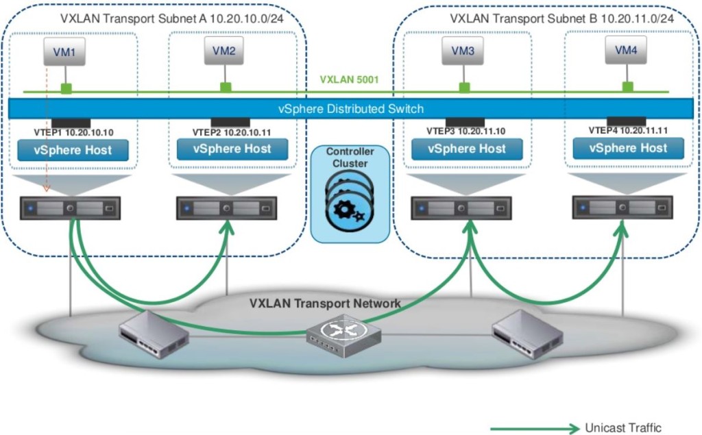
- VXLAN traffic can be sent between VTEPs (below) in 3 different modes
- Unicast – Default option that is supported with vSphere 5.5 and above. This has a slightly more overhead on the VTEPs
- Multicast – Supported with ESXi 5.0 and above. Relies in the Multicasting being fully configured on the transport network with L2-IGMP and L3-PIM
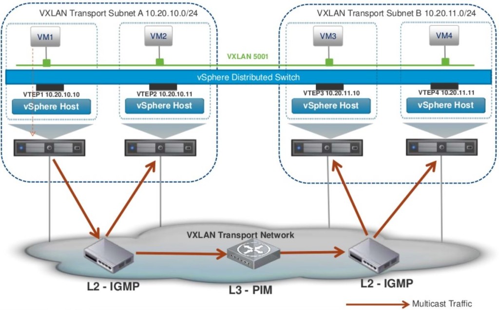
- Hybrid – Unicast for remote traffic and Multicast for local segment traffic.

- Unicast – Default option that is supported with vSphere 5.5 and above. This has a slightly more overhead on the VTEPs
- Within NSX, VXLAN is an overlay network only between ESXi hosts and VM’s have no information of the underlying VXLAN fabric.
- VNI – VXLAN Network Identifier (similar to a VLAN ID)
- Each VXLAN network identified by a unique VNI is an isolated logical network
- Its a 24 bit number that gets added to the VXLAN frame which allows a theoretical limit of 16 million separate networks (but note that in NSX version 6.0, the only supported limit is 20,000 NOT 16 million as VMware marketing may have you believe)
- The VNI uniquely identifies the segment that the inner Ethernet frame belongs to
- VMware NSX VNI range starts from 5000-16777216
- VTEP – VXLAN Tunnel End Point
- VTEP is the end point that is responsible for encapsulating the L2 Ethernet frame in a VXLAN header and forward that on to the transport network as well as the reversal of that process (receive an incoming VXLAN frame from the transport network, strip off everything and just forward on the original L2 Ethernet frame to the virtual network)
- Within NSX, a VTEP is essentially a VMkernal port group that gets created on each ESXi server automatically when you prepare the clusters for VXLAN (which we will do later on)
- A VTEP proxy is a VTEP (specific VMkernal port group in a remote ESXi server) that receive VXLAN traffic from a remote VTEP and then forward that on to its local VTEPs (in the local subnet). The VTEP proxy is selected by the NSX controller and is per VNI.
- In Unicast mode – this proxy is called a UTEP
- In Multicast or Hybrid mode – this proxy is called MTEP
- Transport Zone
- Transport zone is a configurable boundary for a given VNI (VXLAN network segment)
- Its like a container that house NSX Logical Switches created along with their details that present them to all hosts (across all clusters) that are configured to be a part of that transport zone (if you want to restrict certain hosts from seeing certain Logical switches, you’d have to configure multiple Transport Zones)
- Typically, a single Transport Zone across all you vSphere clusters (managed by a single vCenter) is sufficient.
- VXLAN – Virtual Extensible LAN
-
Logical Switch Architecture – Key Points
- Logical Switch within NSX is a virtual network segment which is represented on vSphere via a distributed port group tagged with a unique VNI on a distributed switch.
- Logical Switch can also span distributed switch by associating with a port group in each distributed switch.
- VMotion is supported amongst the hosts that are part of the same vDS.
- This distributed port group is automatically created when you add a Logical Switch, on all the VTEPs (ESXi hosts) that are part of the same underlying Transport Zone.
- A VM’s vNIC then connects to each Logic Switch as appropriate.


VXLAN Network Preparation
- First step involved is to prepare the hosts. (Host Preparation)
- Launch vSphere web client, go to Netwrking & Security -> Installation (left) and click on Host preparation tab

- Select the Compute & Edge clusters where the NSX controllers & compute & edge VM’s reside where you need to enable VXLAN and click install.

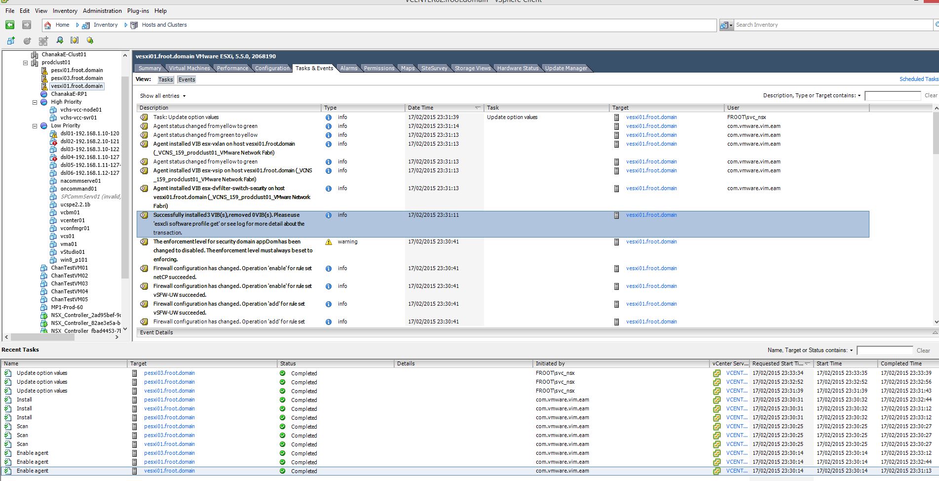
- While the installation is taking place, you can monitor the progress of vSphere web / c# client

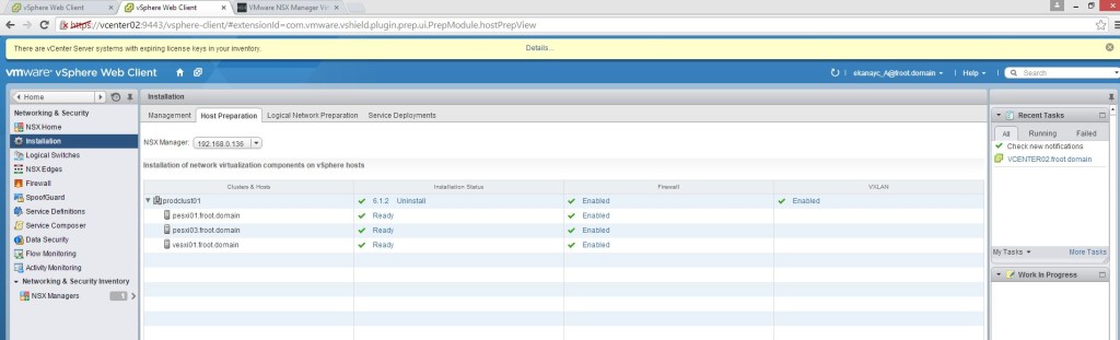
- During this host preparation, 3 VIB’s will be installed on the ESXi servers (as mentioned in the previous post of this series) & you can notice this in vSphere client.

- Once complete, it will be shown as Ready under the installation status as follows

- Launch vSphere web client, go to Netwrking & Security -> Installation (left) and click on Host preparation tab
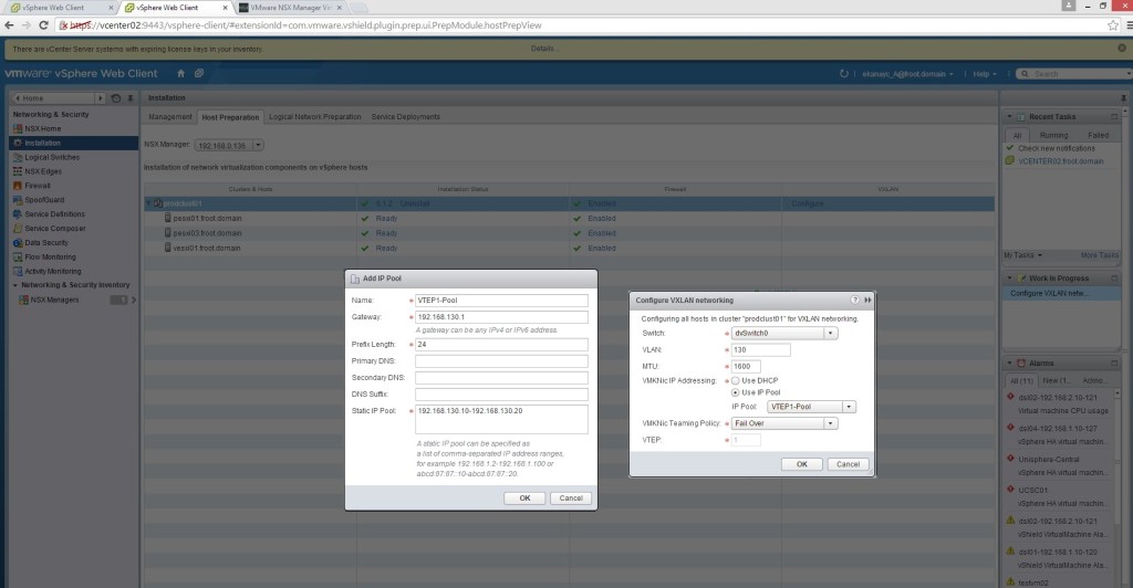
- Configure the VXLAN networking
- Click configure within the same window as above (Host Preparation Tab) under VXLAN. This is where you configure the VTEP settings including the MTU size and if the VTEP connectivity is happening through a dedicated VLAN within the underlying transport network. Presumably this is going to be common as you still have your normal physical network for all other things such as VMotion network (vlan X), storage network (vlan Y)…etc.
- In my example I’ve configured a dedicated VXLAN VLAN in my underlying switch with the MTU size set to 9000 (this could have been slightly more than 1600 for VXLAN to work).
- In a corporate / enterprise network, ensure that this vlan has the correct MTU size specified and also in any other vlans that the remote VTEP are tagged with. The communication between all VTEPs across vlans need to have at least MTU 1600 end to end.
- You also create an IP pool for the VTEP VMkernal port group to use on each ESXi host. Ensure that there’s sufficient capacity for all the ESXi hosts.
- Once you click ok, you can see on vSphere client / web client the creation of the VTEP VMkernal portgroup with an IP assigned from the VTEP Pool defined along with the appropriate MTU size (Note that I’ve only set MTU 1600 in the previous step but it seems to have worked out that my underlying vDS and the physical network is set to MTU 9000 and used that here automatically).

- Once complete, VXLAN will appear as complete under the host preparation tab as follows
- In Logical Network Preparation tab, you’ll notice that the VTEP vlan and the MTU size with all the VMkernal IP assignment for that VXLAN transport network as show below

- Click configure within the same window as above (Host Preparation Tab) under VXLAN. This is where you configure the VTEP settings including the MTU size and if the VTEP connectivity is happening through a dedicated VLAN within the underlying transport network. Presumably this is going to be common as you still have your normal physical network for all other things such as VMotion network (vlan X), storage network (vlan Y)…etc.
- Create a segment ID (VNI pool) – Go to Segment ID and provide a range for a pool of VNI’s

- No go to the Transport Zone tab and create a Global transport zone.

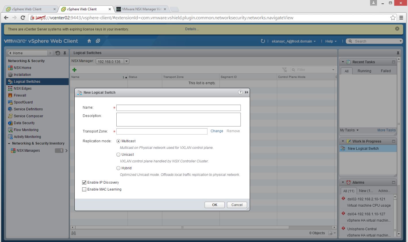
- The logical switch is created using the section on the left and create a logical switch. Provide a name and the transport zone and select the Multicast / Unicast / Hybrid mode as appropriate (my example uses Unicast mode).
- Enable IP discovery: Enables the ARP suppression available within NSX. ARP traffic is generated as a broadcast in a network when the destination IP is known but not the MAC. However within NSX, the NSX controller maintains and ARP table which negates the use of ARP broadcast traffic.
- Enabled MAC learning: Useful if the VM’s have multiple MAC addresses or using vmnics with trunking. Enabling MAC Learning builds a VLAN/MAC pair learning table on each vNic. This table is stored as part of the dvfilter data. During vMotion, dvfilter saves and restores the table at the new location. The switch then issues RARPs for all the VLAN/MAC entries in the table.

- You can verify the creation of the associated port group by looking at the vSphere client.

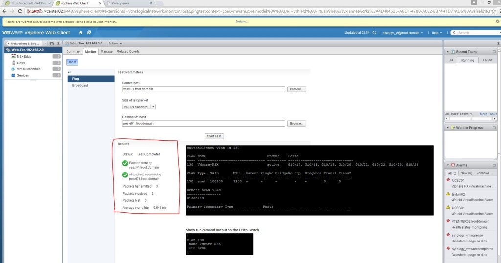
- In order to confirm that your VTEPs (behind the logical switches) are fully configured and can communicate with one another, you can double click the logical switch created, go to monitor and do a ping test using 2 ESXi servers. Note that the switch ports where the uplink NIC adaptors plugged in to need to be configured for appropriate MTU size (as shown)
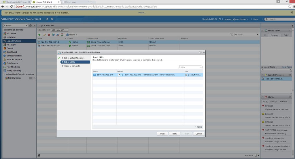
- You can create multiple Logical Switches as required. Once created, select the logical switch and using Actions menu, select add VM to migrate a VM’s networking connectivity to the Logical switch.


There you have it. your NSX environment now has Logical switches that all your existing and new VM’s should be connecting to instead of standard or distributed switches.
As it stands now, these logical networks are somewhat unusable as they are isolated bubbles and the traffic cannot go outside of these networks. Following posts will look at introducing NSX routing using DLR – Distributed Logical Routers to route between different NXLAN networks (Logical switches) and introducing Layer 2 bridging to enable traffic within the Logical Switch network to communicate with the outside world.
Thanks
Chan